Drive device for screw centrifuges

a technology of screw centrifuge and drive device, which is applied in the direction of centrifuges, rotary centrifuges, etc., can solve the problem of high compactness of the drive device, and achieve the effects of compact structure, high flexibility, and optimal efficiency

Inactive Publication Date: 2006-01-19
HILLER
View PDF8 Cites 8 Cited by
  • Summary
  • Abstract
  • Description
  • Claims
  • Application Information

AI Technical Summary

Benefits of technology

[0009] A drive device of this type consumes very little energy and offers optimal efficiency. It is characterized by high flexibility with respect to the choice of operating speeds while having a compact structure. Because the electric torque motor which is disconnected from the drum drive motor rotates along with the drum, the drive device is highly compact. Furthermore, since there is no hydraulic motor for the screw drive, there is no risk of leakage, which is particularly important in the food product area.

Problems solved by technology

Because the electric torque motor which is disconnected from the drum drive motor rotates along with the drum, the drive device is highly compact.

Method used


Image

  • Drive device for screw centrifuges
  • Drive device for screw centrifuges
  • Drive device for screw centrifuges

Examples


Embodiment Construction

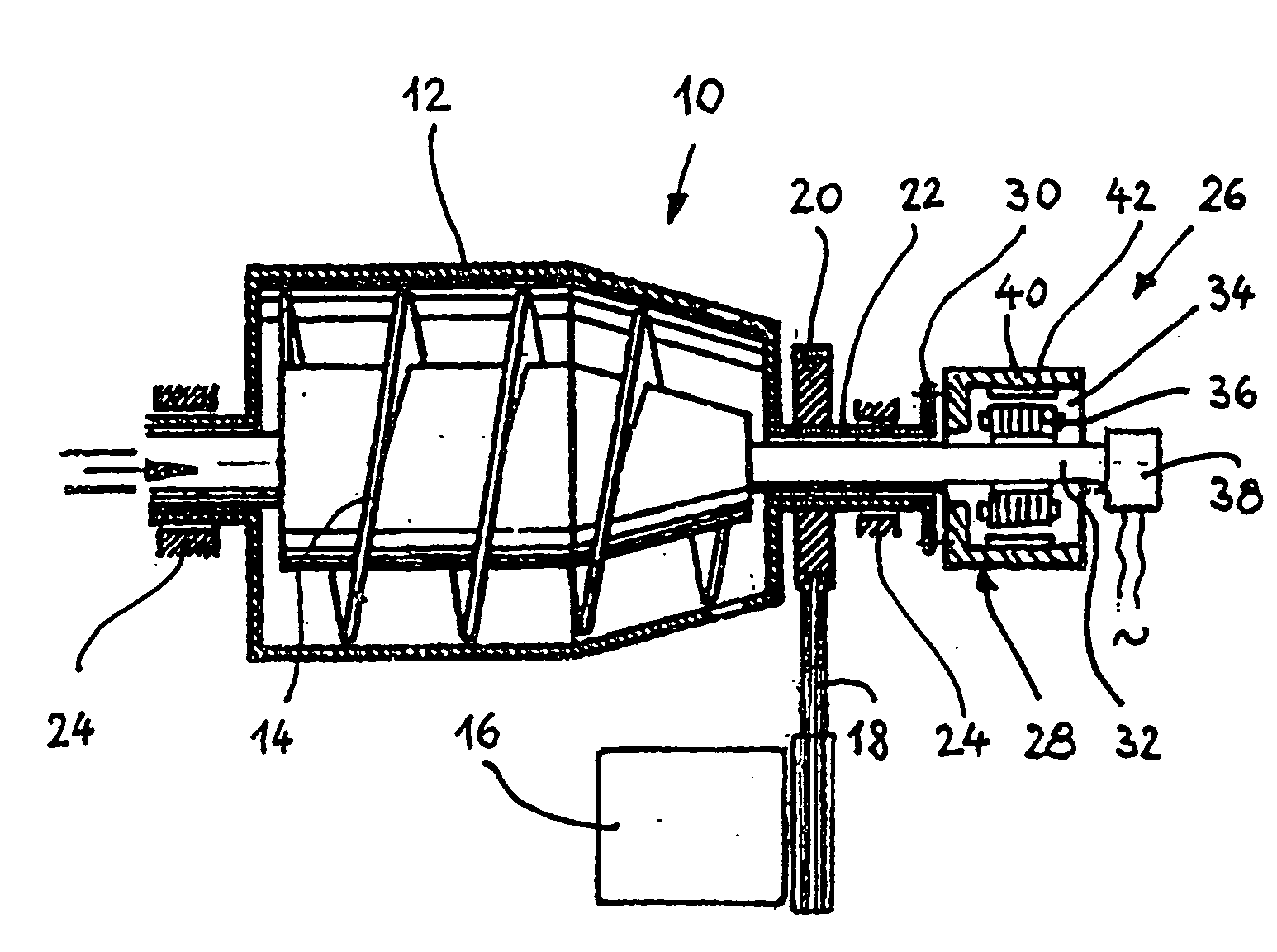
[0022]FIG. 1 shows a longitudinal cross section through a screw centrifuge 10 with a rotating drum 12, in which a screw 14 is supported. The drum 12 is rotated by an electric motor 16, which sets a V-belt pulley 20 in rotation by way of V-belts 18. The pulley is pushed onto a hollow shaft 22, which is permanently connected to the drum 12. The drum 12 is supported rotatably at the ends in bearings 24 in the standard manner.

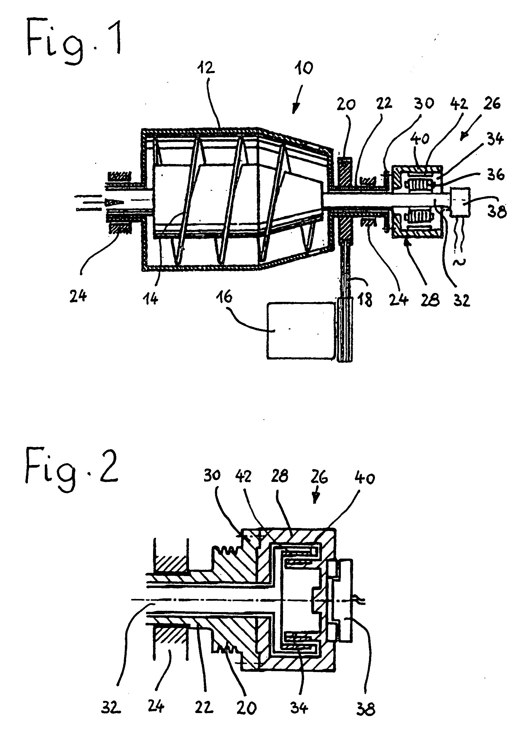
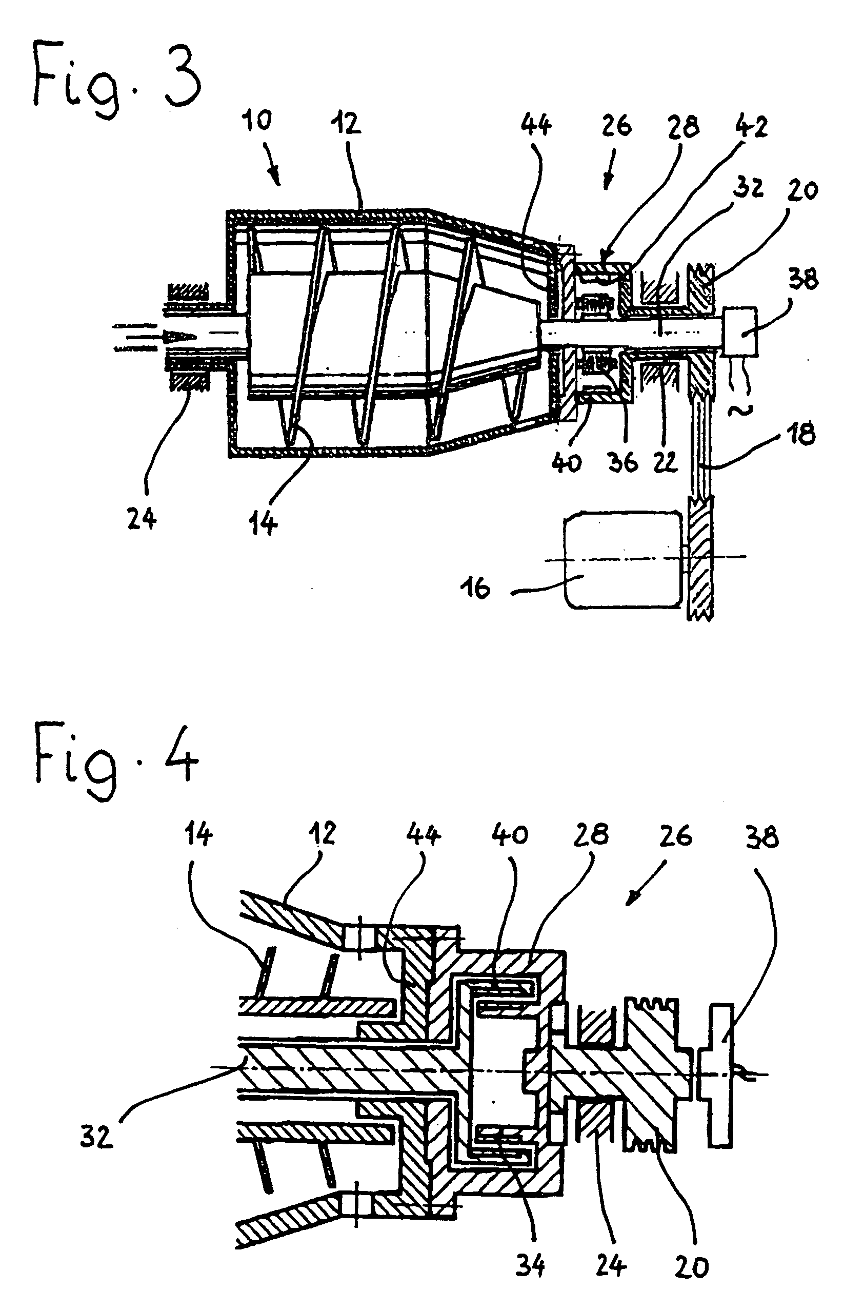
[0023] A multipolar torque motor 26 is used to rotate the screw 14. The housing 28 of the motor is permanently connected to the drum 12 by way of a flange 30 of the hollow shaft 22 and is disconnected from the motor 16. The shaft 32 of the screw 14 passes through the hollow shaft 22. The stator 34 of the torque motor 26 carries a plurality of coils 36, which are supplied with current by way of a slip-ring induction motor 38, and is pushed onto the shaft 32 of the screw 14.

[0024] The housing 28 of the torque motor 26 is designed as an external rotor 40, the cylind...


PUM


Abstract

A drive device for screw centrifuges has a rotating drum driven by a drum driving motor, and a screw mounted coaxially in the drum and having a screw shaft. A screw drive motor for rotating the screw has a housing rotatably fixed to the drum and an electric torque motor rotatably fixed to the screw shaft and disconnected from the drum driving motor.

Description

BACKGROUND OF THE INVENTION [0001] 1. Field of the Invention [0002] The invention pertains to a drive device for screw centrifuges with a rotating, motorized drum and a screw. [0003] 2. Description of the Related Art [0004] Various systems for driving screw centrifuges are known. The simplest drive is a gearbox drive, in which an electric motor drives the drum by a first V-belt, whereas a second V-belt, operating in parallel with the first, causes the screw to rotate by way of a planetary gear train. The planetary gear train is used to produce the speed differential for the screw. With this drive, the two rotational speeds can be varied independently of each other. For this purpose, the system must be stopped, and one of the two pairs of V-belts must be replaced. [0005] Another concept is the so-called “hybrid” drive, in which an electric motor drives the drum via replaceable V-belts, whereas a hydraulic motor is provided to drive the screw. Thus the speed differential can be varied...

Claims


Application Information

Patent Timeline
Patent Type & Authority Applications(United States)
IPC IPC(8): B04B9/00B04B1/20
CPCB04B9/04B04B1/2016
Inventor HAIDER, GUNTER
Owner HILLER
Why Eureka
Try Eureka