Vertical and horizontal dual-purpose steel ladle tilting mechanism

A technology of vertical and horizontal dual-purpose, tipping mechanism, which is applied in casting melt containers, metal processing equipment, casting equipment, etc. Effects of normal production process

Active Publication Date: 2015-04-29
WUXI JULI HEAVY IND OFF
View PDF7 Cites 4 Cited by
  • Summary
  • Abstract
  • Description
  • Claims
  • Application Information

AI Technical Summary

Problems solved by technology

[0003] In view of the above problems, the present invention provides a vertical and horizontal ladle tilting mechanism, which can solve the problem that the auxiliary hook of the crane is d

Method used


Image

  • Vertical and horizontal dual-purpose steel ladle tilting mechanism
  • Vertical and horizontal dual-purpose steel ladle tilting mechanism
  • Vertical and horizontal dual-purpose steel ladle tilting mechanism

Examples


Embodiment Construction

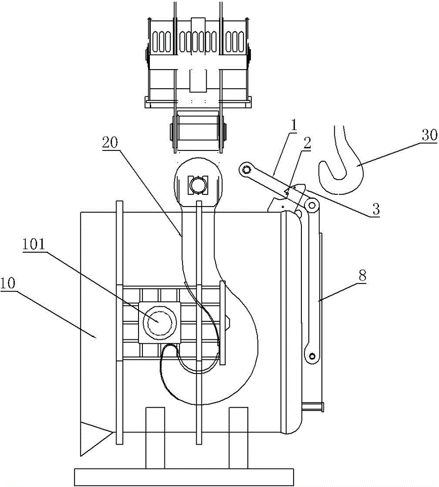
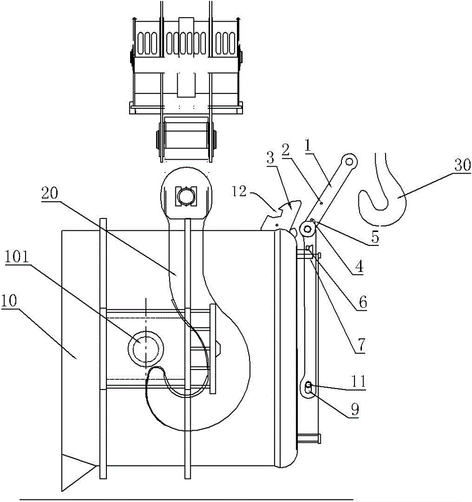
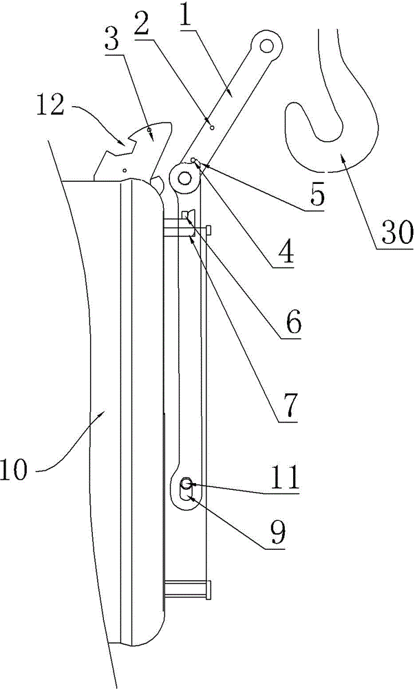
[0017] See figure 2 , image 3 and Figure 4 The ladle tipping mechanism of the present invention comprises a pull rod 1 and a connecting rod 8. One end of the connecting rod 8 is rotatably mounted on the bottom side of the ladle 10, and the other end is rotatably connected to the pull rod 1. The pull rod 1 is provided with a first hanging shaft 2, and the ladle The side of the bottom of 10 is fixedly equipped with pull rod support 3, pull rod support 3 has limit gap 12, when the ladle is vertically laid flat, the first hanging shaft 2 is limited by the limit gap 12, and connecting rod 8 is positioned at the bottom side of steel ladle 10. The rotatable connection end is provided with a long waist hole 9 extending along the length direction of the connecting rod, and the bottom side of the steel ladle 10 is fixed with a pin shaft 11, and the connecting rod 8 is rotatably connected and installed on the steel ladle 10 through the pin shaft 11 and the long waist hole 9 The side...


PUM


Abstract

The invention provides a vertical and horizontal dual-purpose steel ladle tilting mechanism which can solve the problems that a secondary hook of an overhead crane is difficult to advance and retreat or cannot advance and retreat when an existing tilting mechanism lifts a steel ladle after the steel ladle is horizontally placed, and can ensure the normal lifting of the steel ladle and the smelting and production. The tilting mechanism comprises a pull rod and a connecting rod, wherein one end of the connecting rod is rotationally arranged at one bottom side of the steel ladle, and the other end of the connecting rod is rotationally connected with the pull rod; the pull rod is provided with a first hanging shaft, the bottom angle end of the steel ladle is fixedly provided with a pull rod support, a limit gap is formed in the pull rod support, and the first hanging shaft is limited by the limit gap when the steel ladle is placed horizontally. The tiling mechanism is characterized in that the rotary connecting end of the connecting rod is provided with an oblong hole extending in a length direction of the connecting rod at one bottom side of the steel ladle, the bottom side of the steel ladle is fixedly provided with a hinge pin, the oblong hole is rotationally connected and installed at the bottom side of the steel ladle, the steel ladle and the connecting hole are provided with a connecting rod limit structure, and the connecting rod and the pull rod are further provided with a pull rod limit structure.

Description

technical field [0001] The invention relates to the field of metallurgical equipment, in particular to a vertical and horizontal ladle tipping mechanism. Background technique [0002] Usually, the tipping of the ladle is to use the auxiliary hook of the crane to pull the tipping mechanism installed at the bottom of the ladle. Through the cooperation of the main and auxiliary hooks of the crane, the ladle can be turned over smoothly to realize the dumping of molten steel or steel slag in the ladle. When the ladle is overturned, the main hook 10 of the crane hooks the trunnions 101 on both sides of the ladle to lift the ladle to the tipping height, and the auxiliary hook of the crane hooks the pull rod 1 of the tipping mechanism, and then drives the connecting rod at the bottom of the ladle by pulling the pull rod 1 to rotate 8 Drive the ladle 10 to tip over stably. In the storage state where the ladle cannot be hoisted, the pull rod and connection must be firmly anchored on t...

Claims


Application Information

Patent Timeline
IPC IPC(8): B22D41/06
CPCB22D41/06
Inventor 华志坚王凤良
Owner WUXI JULI HEAVY IND OFF
Why Eureka
Try Eureka