Eureka AIR delivers breakthrough ideas for toughest innovation challenges, trusted by R&D personnel around the world.

High-voltage common-rail electrically-controlled oil sprayer

An electronically controlled fuel injection, high-pressure common rail technology, applied in the machine/engine, fuel injection device, engine components, etc., can solve the large downward impact force of the throttle orifice, increase the manufacturing cost of the solenoid valve, and the shape and position tolerance requirements High problems, to achieve the effect of reducing downward impact force, facilitating assembly and maintenance, and reducing geometrical tolerance requirements

Inactive Publication Date: 2016-06-15
宁波舜田良源油嘴油泵有限公司
View PDF8 Cites 2 Cited by
  • Summary
  • Abstract
  • Description
  • Claims
  • Application Information

AI Technical Summary

Problems solved by technology

This structure has the following disadvantages: 1. The fuel injector body must be carburized and quenched, and the guide hole must have sufficient hardness, which results in high manufacturing costs; after a certain period of use, the joint between the fuel injector body and the control piston is worn out, The fuel injector body is scrapped, and the use cost is high
2. The plane sealing structure is adopted between the lower end surface of the armature rod in the armature assembly and the upper end surface of the oil return orifice of the orifice plate, which inevitably makes the shape and position tolerance requirements of each related part high enough and the manufacturing cost is high
3. There is no buffer spring in the downward movement of the armature assembly, which will generate a large downward impact on the throttle orifice
4. The air gap between the upper end surface of the armature and the lower end surface of the iron core in the solenoid valve assembly is controlled by the height of the small boss on the upper end surface of the armature, and has no adjustability; moreover, there is an impact force on the iron core of the solenoid valve, increasing Solenoid valve manufacturing cost

Method used


Image

  • High-voltage common-rail electrically-controlled oil sprayer
  • High-voltage common-rail electrically-controlled oil sprayer
  • High-voltage common-rail electrically-controlled oil sprayer

Examples


Embodiment Construction

[0026] The present invention will be further described in detail below in conjunction with the accompanying drawings and embodiments.

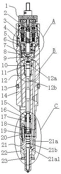
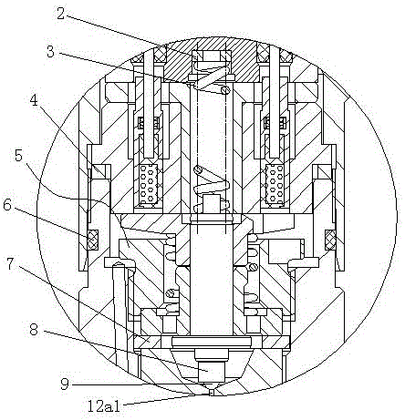
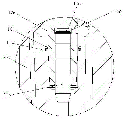
[0027] like Figure 1 to Figure 8 Shown is the structural representation of the present invention,

[0028] The reference signs are: solenoid valve assembly 1, solenoid valve tight cap 1b, electromagnet spring adjustment washer 2, electromagnet spring 3, air gap adjustment washer 4, armature assembly 5, armature 5a, compression screw 5b, tightening hole 5b1, buffer spring 5c, guide sleeve 5d, armature shaft 5e, tight cap seal ring 6, armature lift adjustment washer 7, ball seat 8, steel ball 9, seal ring 10, support ring 11, valve assembly 12, control valve 12a, oil return orifice 12a1, oil inlet orifice 12a2, valve control chamber 12a3, control piston 12b, O-ring 13, injector body 14, spring upper seat 15, nozzle spring adjustment washer 16, nozzle spring 17 , Push rod 18, positioning pin 19, lift limit block 20, fuel injector coupler 21, n...


PUM


Abstract

The invention discloses a high-voltage common-rail electrically-controlled oil sprayer. The high-voltage common-rail electrically-controlled oil sprayer comprises an oil sprayer body, wherein a valve assembly formed by a control valve and a control piston is assembled in the oil sprayer body, an armature assembly is arranged above the control valve, an armature lift-range adjusting washer is arranged between the armature assembly and the control valve, and an electromagnetic valve assembly is arranged above the armature assembly; and an oil return throttling hole of the control valve is cooperated with a steel ball, the lower end of the control piston is cooperated with an ejector rod, an oil nozzle spring sleeves the ejector rod, an oil spraying nozzle mated part is arranged below the ejector rod, an oil spraying nozzle tightening cap sleeves the oil spraying nozzle mated part, and the oil spraying nozzle tightening cap is connected with the lower end of the oil sprayer body in a screwing manner. The high-voltage common-rail electrically-controlled oil sprayer has the advantages of reasonability in structure, convenience in assembly and repair, convenience in clearance adjustment, low production cost and long service life.

Description

technical field [0001] The invention relates to the technical field of diesel engine electronic control, in particular to a high-pressure common rail electronic control fuel injector. Background technique [0002] With the increasing requirements of global humans on diesel engine emissions and economy, the traditional mechanical diesel fuel injection system has been unable to meet the existing needs. The development of electronic control technology promotes the three leaps in the development of diesel fuel injection system, among which the high-pressure common rail fuel injection system realizes flexible control such as high-pressure injection, independent fuel injection timing, fuel injection rate, etc., which improves economy, power and reliability It will become the development trend of electronically controlled diesel engine fuel injection system. At present, domestic manufacturers of high-pressure common rail electronically controlled fuel injectors all adopt the follo...

Claims


Application Information

Patent Timeline
IPC IPC(8): F02M63/00F02M63/02F02M61/10
CPCF02M63/0019F02M61/10F02M63/0022F02M63/0056F02M63/0059F02M63/007F02M63/0075F02M63/0225
Inventor 周书田周文良
Owner 宁波舜田良源油嘴油泵有限公司
Why Eureka
Eureka Blog
Learn More