Fuel cell stack bandage type pressing assembly structure and design method thereof

A fuel cell stack and assembly structure technology, which is applied to fuel cells, circuits, electrical components, etc., can solve the problems of unstable expansion and contraction rate, uneven current distribution, inconvenient maintenance and maintenance, and achieves compact structure and current distribution. The effect of uniformity and thickness variation

Pending Publication Date: 2019-08-30
众泰新能源汽车有限公司
View PDF0 Cites 11 Cited by
  • Summary
  • Abstract
  • Description
  • Claims
  • Application Information

AI Technical Summary

Problems solved by technology

[0005] The invention mainly solves the deficiencies of poor sealing, uneven current distribution, flammability, unstable expansion and contraction rate, short service life and inconvenient maintenance in the prior art, and provides a fuel cell stack strap-type compression The assembly structure and its design method, its fuel cell stack strap-type compression assembly structure has the advantages of compact structure, compression supplement, strong sealing, uniform current distribution, easy assembly and maintenance, and long service life
Its design approach accounts for thickness variations due to tolerance build-up or thermal expansion of components

Method used


Image

  • Fuel cell stack bandage type pressing assembly structure and design method thereof
  • Fuel cell stack bandage type pressing assembly structure and design method thereof
  • Fuel cell stack bandage type pressing assembly structure and design method thereof

Examples


Embodiment

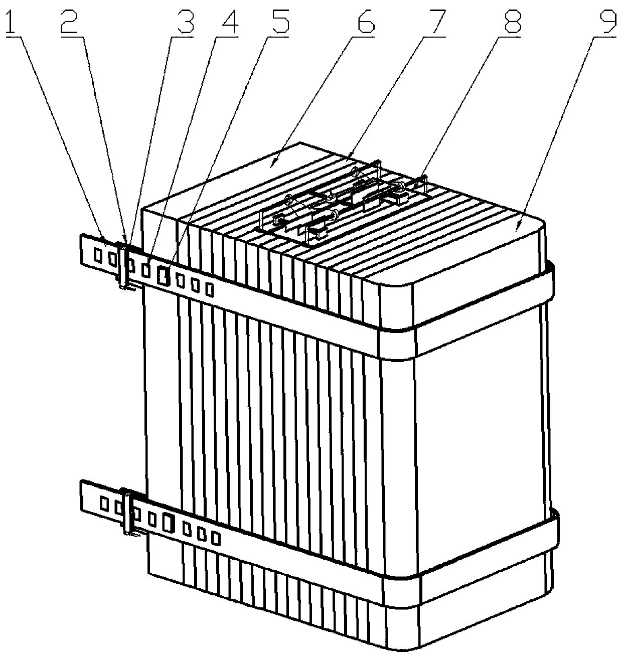
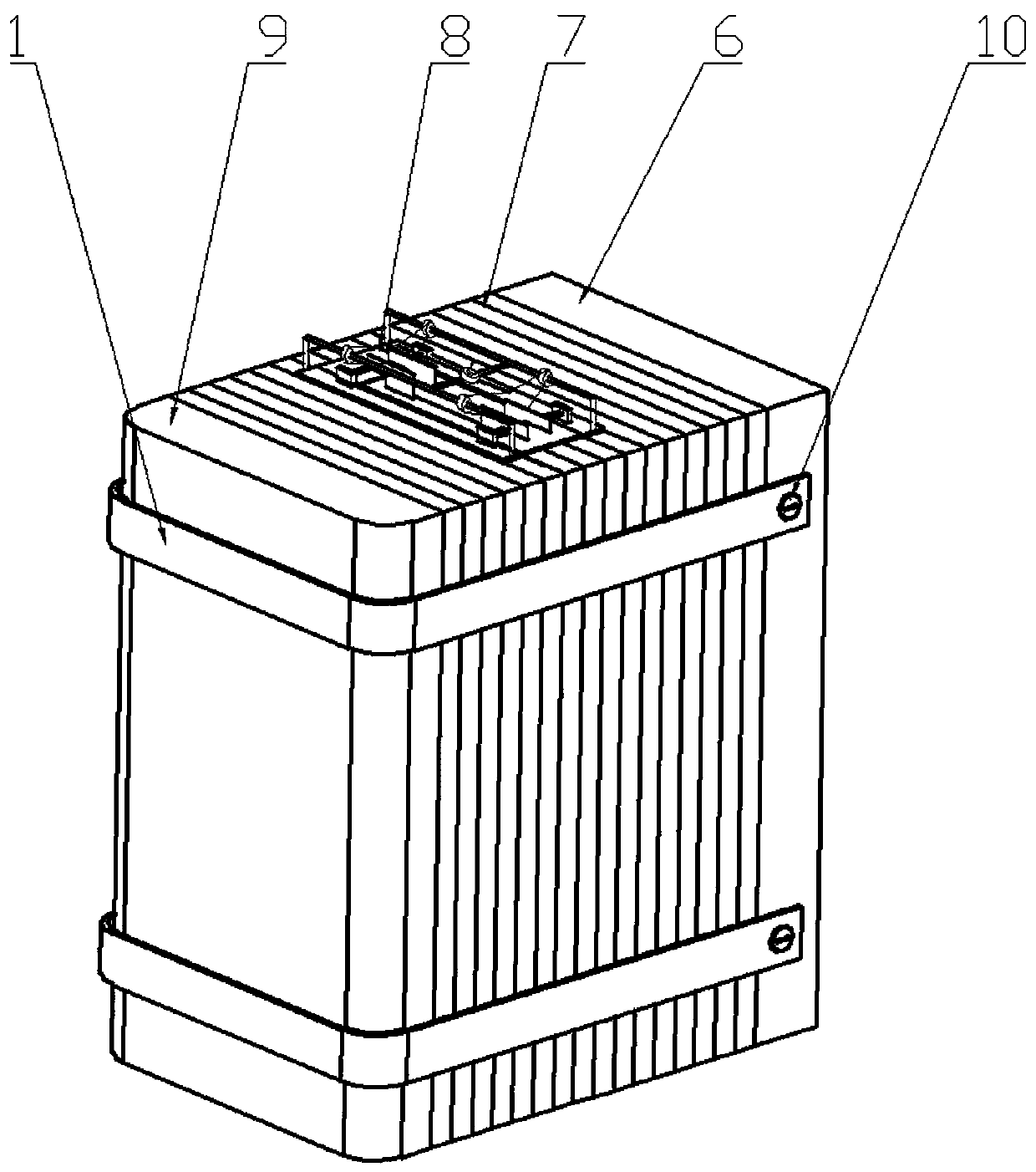
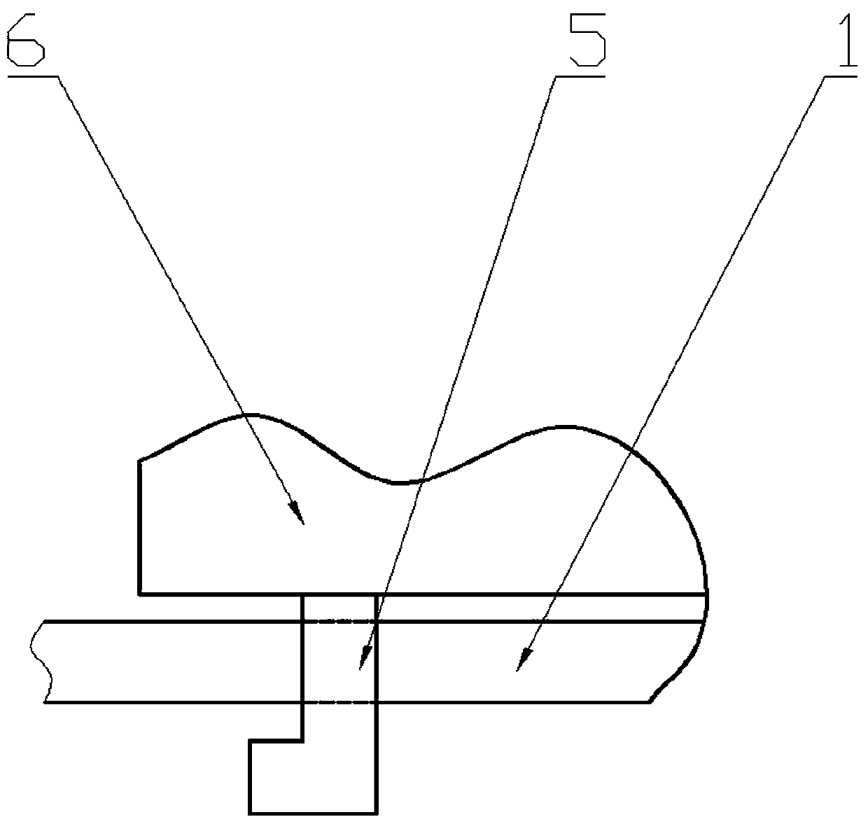
[0031] Example: such as Figure 1-6 As shown, a fuel cell stack strap-type compression assembly structure includes 16 fuel cells 7, one end of the fuel cell 7 is provided with a main end plate 6, the other end of the fuel cell is provided with an auxiliary end plate 9, and the main end plate 6 Two compression bands 1 are arranged between the outer wall and the outer wall of the auxiliary end plate 9, and a fixing screw 10 is threadedly connected and fixed to the main end plate 6 between one end of the compression band 1 and the outer wall of the main end plate 6, and the other end of the compression band 1 is connected to the outer wall of the main end plate 6. The outer wall of the main end plate 6 is provided with a hook pin 5 that is engaged and fixed with the main end plate 6 , and the compression belt 1 is provided with 8 belt holes 4 that are movable and limit nested with the hook pin 5 . The rear end of the hook pin 5 is provided with a clamping frame 2 integrated with ...


PUM


Abstract

The invention relates to a fuel cell stack bandage type pressing assembly structure and a design method thereof and belongs to the technical field of fuel cells. The structure comprises multiple fuelcells. A main end plate is arranged at one end of the fuel cells and an auxiliary end plate is arranged at the other end of the fuel cells. A plurality of compression belts are arranged between the outer wall of the main end plate and the outer wall of the auxiliary end plate. A fixing screw in threaded connection and fixation with the main end plate is arranged between one end of each compressionbelt and the outer wall of the main end plate. A hook pin fixedly connected with the main end plate in a clamped and embedded mode is arranged between the other end of each compression belt and the outer wall of the main end plate. A plurality of belt holes are formed in the compression belts. A plurality of gap adjusting springs are arranged between the auxiliary end plate and the fuel cells, and spring gaskets are arranged between the gap adjusting springs and the auxiliary end plate. The assembly structure has the advantages of compact structure, compression supplement, high sealing performance, uniform current distribution, easiness in assembly and maintenance and long service life. The repeatability of the assembly structure is improved, and the structural pressure uniformity is improved. The influence of manufacturing tolerance and change of raw material size on the structural size precision is avoided.

Description

technical field [0001] The invention relates to the technical field of fuel cells, in particular to a fuel cell stack strap-type compression assembly structure and a design method thereof. Background technique [0002] A fuel cell is a chemical device that directly converts the chemical energy of fuel into electrical energy, also known as an electrochemical generator. It is the fourth power generation technology after hydropower, thermal power and atomic power. Since the fuel cell converts the Gibbs free energy in the chemical energy of the fuel into electrical energy through an electrochemical reaction, it is not limited by the Carnot cycle effect, so the efficiency is high. Low-temperature fuel cells run on hydrogen fuel and produce only water, making them an ideal technology for zero-emission mobility. State-of-the-art fuel cells use a proton exchange membrane to transport protons from the anode (where hydrogen is split into protons and electrons) to the cathode (where ...

Claims


Application Information

Patent Timeline
Patent Type & Authority Applications(China)
IPC IPC(8): H01M8/2404H01M8/2465H01M8/247
CPCH01M8/2404H01M8/2465H01M8/247Y02E60/50Y02P70/50
Inventor 欧绍辉马德仁洪燕贾悦
Owner 众泰新能源汽车有限公司
Why Eureka
Try Eureka