Control mechanism mounting structure of laser welding device

A control mechanism, laser welding technology, applied in laser welding equipment, welding equipment, manufacturing tools, etc., can solve the problems of affecting work efficiency, inconvenient use, occupying the use space of the console, etc., to achieve convenient use and avoid production efficiency. effect of influence

Inactive Publication Date: 2015-04-29
CHONGQING TONGDA ENERGY EQUIP
View PDF0 Cites 0 Cited by
  • Summary
  • Abstract
  • Description
  • Claims
  • Application Information

AI Technical Summary

Problems solved by technology

[0003] However, the existing laser welding control mechanism is often installed on the welding workbench in a built-in or directly placed manner, which not only occupies the use space of the operation table, but also is inconvenient to use during the welding process, affecting work efficiency

Method used


Image

  • Control mechanism mounting structure of laser welding device
  • Control mechanism mounting structure of laser welding device

Examples


Embodiment Construction

[0015] The specific implementation manner and working principle of the present invention will be further described in detail below in conjunction with the accompanying drawings.

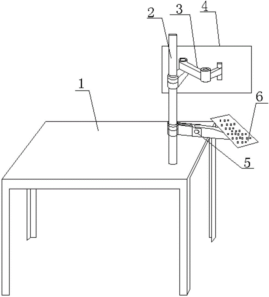
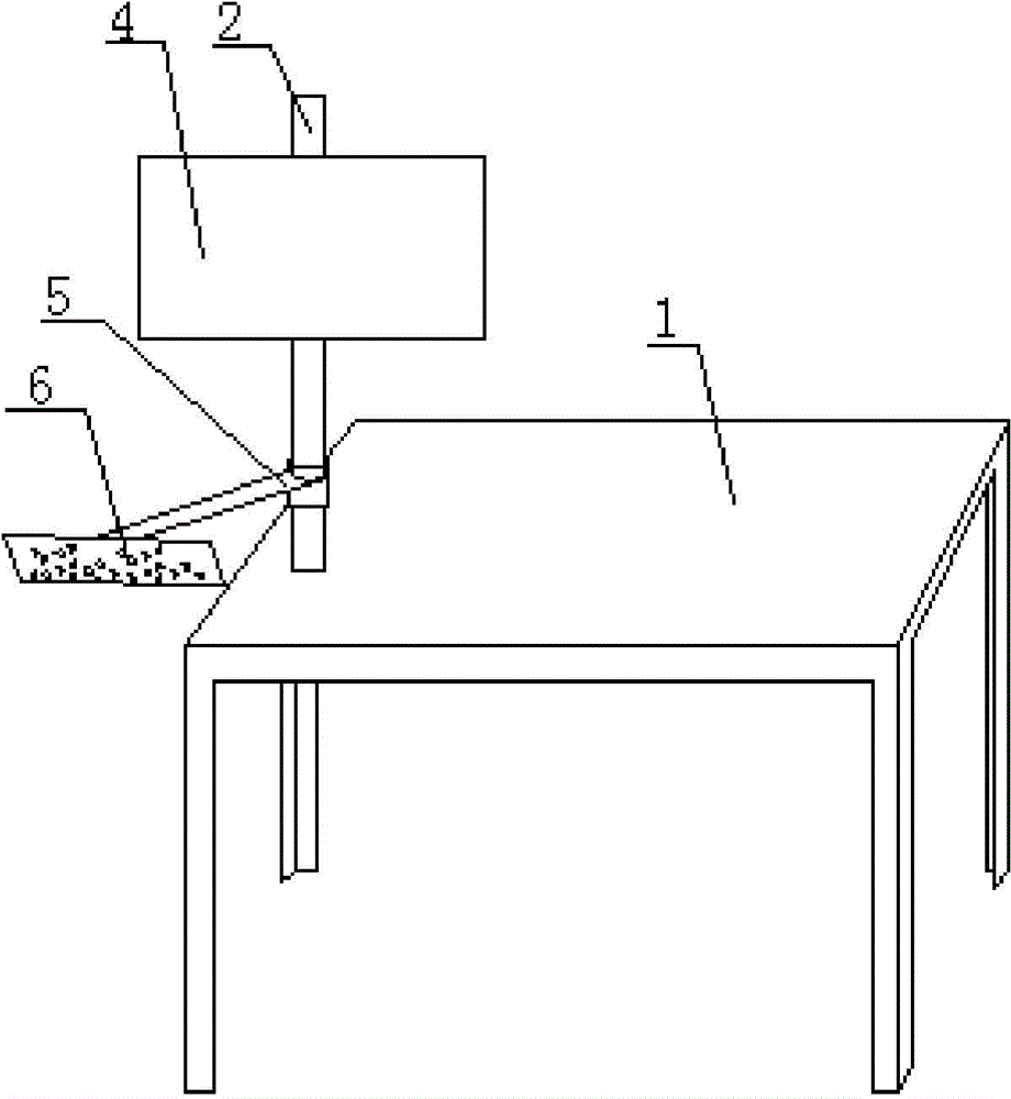
[0016] Such as Figure 1-Figure 2 As shown, a control mechanism installation structure of a laser welding device includes a base 1 and a control mechanism 6, a column 2 is arranged on the base 1, and the control mechanism 6 is connected to the lower part of the column 2 through a support rod 3 The input module 4, the upper part of the column 2 is hinged with a connecting rod 5, and the other end of the connecting rod 5 is hinged with the control mechanism 6.

[0017] See attached figure 1 , the support rod 3 includes a first support rod and a second support rod, one end of the first support rod is hinged to one end of the second support rod, and the other end of the first support rod is connected to the column 2 Fixedly connected, the other end of the second support rod is connected with the input ...


PUM


Abstract

The invention discloses a control mechanism mounting structure of a laser welding device. The control mechanism mounting structure comprises a base and a control mechanism. The control mechanism mounting structure is characterized in that the base is provided with an upright column; the lower part of the upright column is connected with an input module of the control mechanism by virtue of a support rod; the upper part of the upright column is articulated with a connecting rod, and the other end of the connecting rod is articulated with the control mechanism. The control mechanism mounting structure has the obvious effects that the control mechanism is supported by the upper part of one side of an operation desk without occupying the space of the operation desk, so that influence on the production efficiency is avoided and the control mechanism mounting structure is convenient to use; by virtue of an articulation mode, the position of the control mechanism can be changed randomly.

Description

technical field [0001] The invention relates to the technical field of laser welding, in particular to a control mechanism installation structure of a laser welding device. Background technique [0002] Laser welding is a new type of welding processing method, mainly for precision parts welding of thin-walled materials, which can realize butt welding, sealing welding, spot welding, lap welding, etc., with small weld width, high depth-to-width ratio, small heat-affected zone, The deformation is small, the welding speed is fast, the weld seam is flat and beautiful, no treatment is required or only simple treatment is required after welding, the weld seam quality is high, there is no air hole, the positioning accuracy can be precisely controlled, the focusing light spot is small, and it is easy to realize welding automation. Therefore, it is widely used in various fields of industry. [0003] However, the existing laser welding control mechanism is often embedded or directly i...

Claims


Application Information

Patent Timeline
Patent Type & Authority Applications(China)
IPC IPC(8): B23K26/70B23K26/21
Inventor 吴浩
Owner CHONGQING TONGDA ENERGY EQUIP
Why Eureka
Try Eureka