
Automobile wheel diversion structure

A technology for wheels and automobiles, applied to superstructures, subassemblies of superstructures, vehicle components, etc., which can solve the problems of large air resistance at the bottom of vehicles, lack of wind guiding and drag reduction effects, and limited effects

Inactive Publication Date: 2015-04-29
常州市领业车辆附件厂
View PDF0 Cites 1 Cited by
  • Summary
  • Abstract
  • Description
  • Claims
  • Application Information

AI Technical Summary

Problems solved by technology

Most of the wind deflectors in use now use a flat plate structure. Although this structure is simple and can reduce wind resistance to a certain extent, the effect is very limited.
And if the length and width of the wind deflector are not designed properly, it may cause greater air resistance at the bottom of the vehicle
Therefore, the flat wind deflector does not have the ideal effect of wind deflecting and reducing drag.

Method used


Image

  • Automobile wheel diversion structure
  • Automobile wheel diversion structure

Examples


Embodiment Construction

[0013] The present invention will be further described below in conjunction with the accompanying drawings.

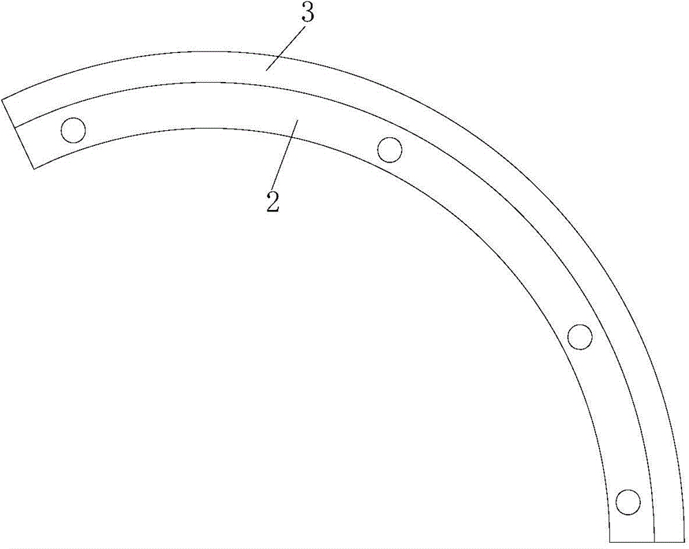
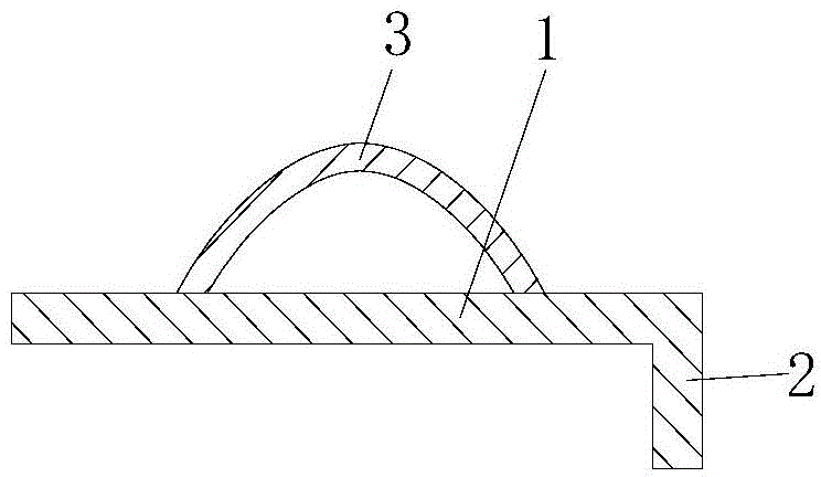
[0014] refer to figure 1 and figure 2 , the automobile wheel deflector structure of the present invention includes a fan-shaped plate 1 and a mounting plate 2 fixed on the fan-shaped plate 1 . The arc of the fan-shaped plate is 90 to 120 degrees, and the arc of the fan-shaped plate in the present invention is 105 degrees. A deflector 3 is arranged in the middle of the outer surface of the arc-shaped plate 1, and the longitudinal section of the deflector 3 is parabolic. The deflector is integrally formed with the fan-shaped plate, or is fixed on the fan-shaped plate by welding. The thickness of the deflector is 4-10mm, and the thickness of the deflector in the present invention is 6mm.


PUM


Abstract

The invention relates to an automobile wheel diversion structure which comprises a fan-shaped plate and a mounting plate fixed on the fan-shaped plate. A diversion plate is arranged in the middle of the upper surface of an arc-shaped plate, and longitudinal section of the diversion plate is parabolic. The automobile wheel diversion structure is conducive to reducing drag coefficient of automobile wheels.

Description

technical field [0001] The invention relates to an automobile wheel flow guide structure. Background technique [0002] In order to reduce the air resistance of automobile running and reduce fuel consumption, existing automobiles have designed many parts with partial air conduction in addition to fully considering the effective conduction of air in the exterior design of the automobile. For example, on some high-end cars and sports cars, a wind deflector is designed in front of the front wheel of the car to guide the airflow in front of the wheel, so that the airflow in front of the wheel does not directly blow to the wheel, reducing the wheel's running resistance. Most of the wind deflectors that have been used at present adopt a flat plate structure. Although the structure is simple, it can reduce the wind resistance to a certain extent, but the effect is very limited. Moreover, if the length and width of the wind deflector are not designed properly, it may cause greater...

Claims


Application Information

Patent Timeline
Patent Type & Authority Applications(China)
IPC IPC(8): B62D25/16
CPCB62D25/16
Inventor 陈叶
Owner 常州市领业车辆附件厂
Learn More