Bicycle fast demounting structure

A bicycle and linkage rod technology, which is applied to bicycle racks, bicycle accessories, transportation and packaging, etc., can solve the problems of time-consuming, loose locking rod 10, poor endurance strength, etc., and achieve the effect of good safety function and stable positioning

Active Publication Date: 2015-04-29
FUL CHEE ENT
View PDF6 Cites 0 Cited by
  • Summary
  • Abstract
  • Description
  • Claims
  • Application Information

AI Technical Summary

Problems solved by technology

[0004] (2) Because the locking handle 13 cannot adjust the left and right angles, and the locking handle needs to be positioned downward against the vehicle frame 16, it must cooperate with the locking of the nut 11 to adjust the locking handle 13 Angle, very troublesome and time-consuming
[0005] (3) In particular, the linkage rod 12 is directly screwed into the screw hole 101 of the lock force lever 10. After the lock force lever 10 is locked, the linkage rod 12 is still connected to the lock force lever 10, so there will be a "lock force handle 13". Turning by mistaken touch" and "vibration during driving" cause the linkage rod 12 to malfunction and make the locking rod 10 loose, which is not safe
[0006] ⑷The positioning seat 15 has no reinforcing structure, and its endurance strength is poor

Method used


Image

  • Bicycle fast demounting structure
  • Bicycle fast demounting structure
  • Bicycle fast demounting structure

Examples


Embodiment Construction

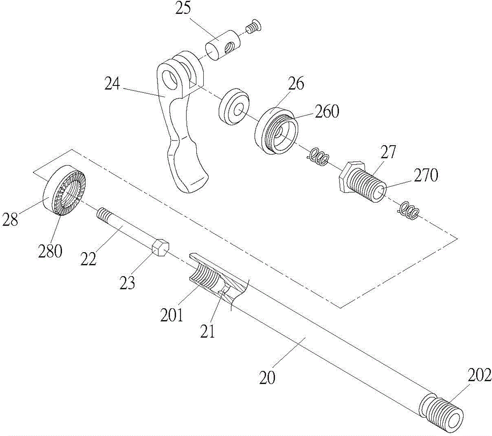
[0032] see image 3 , 4 , 5, 6, the bicycle quick release structure of the present invention comprises: lock force lever 20, linkage lever 22, positioning seat 28, link head 25, lock force handle 24; Linkage lever 22 is connected with link head 25, and is combined in In the locking handle 24, the linkage rod 22 is combined into the locking rod 20, and one end of the locking rod 20 has an external thread 202 and is locked to the frame 17; wherein, the other end of the locking rod 20 is provided with a screw hole 201, a polygonal groove 21 is provided in the screw hole 201; the linkage rod 22 is provided with a polygonal head 23 corresponding to the shape of the polygonal groove 21, and the locking handle 24 can make the linkage rod 22 advance to embed the polygonal head 23 into the locking force The polygonal groove 21 of the rod 20 forms the locking rod 20 that can be driven to rotate, and the linkage rod 22 can also retreat to make the polygonal head 23 break away from the p...


PUM


Abstract

The invention discloses a bicycle fast demounting structure which comprises a locking rod, a linkage rod, a positioning seat, a connector and a locking handle. The linkage rod is connected with the connector and assembled into the locking handle and the locking rod. One end of the locking rod is provided with outer threads for allowing the locking rod to be locked to a frame. The other end of the locking rod is provided with a screw hole. A polygonal groove is formed in the screw hole. A bolt with a through hole is assembled to the screw hole of the locking rod. The bolt penetrates the positioning seat. The linkage rod penetrates the through hole of the bolt. The linkage rod is provided with a polygonal head. The locking handle can allow the linkage rod to move forwardly so as to allow the polygonal head to be embedded into the polygonal groove of the locking rod to form the drivable rotary locking rod. The locking handle can also allow the linkage rod to move backwardly so as to allow the polygonal head to leave the polygonal groove to form the non-rotatable locking rod. The polygonal head of the linkage rod can be embedded into or leave the polygonal groove of the locking handle, so that the locking handle can rotate or cannot rotate, mistaken loosening of the locking rod due to the vibration of the linkage rod of the locking handle is avoided, and safety is increased.

Description

technical field [0001] The invention relates to a bicycle quick-release structure. The locking lever and the linkage lever of the bicycle quick-release structure can be connected and linked when they need to be rotated to lock and loosen. After locking, the locking lever is separated from the locking lever. Therefore, the locking bar will not be loosened due to vibration, so that the safety effect can be achieved. Background technique [0002] Existing bicycle quick release locking force structure is generally all the same figure 1 , 2 Shown, be that a locking force bar 10 wears and assembles on the axle, and its one end is provided with nut 11 and locks on vehicle frame 16, and the other end is provided with interlocking bar 12, locking bar 13, positioning seat 15, and interlocking bar 12 and The combined structure of the locking handle 13 is set so that the linkage rod 12 has a connecting head 14 and is eccentrically combined in the locking handle 13. When the locking ha...

Claims


Application Information

Patent Timeline
Patent Type & Authority Applications(China)
IPC IPC(8): B62K19/00
Inventor 刘育辰
Owner FUL CHEE ENT
Why Eureka
Try Eureka