
Material blocking device of reel

A blocking device and coiling technology, applied in the direction of transportation and packaging, conveyor objects, etc., can solve the problems of not conforming to the concept of intensive equipment manufacturing, increased maintenance workload, and increased equipment investment, etc., to achieve Good benefits, reduced equipment investment, and scientific force effects

Active Publication Date: 2015-04-29
湖南复星合力新材料有限公司
View PDF7 Cites 2 Cited by
  • Summary
  • Abstract
  • Description
  • Claims
  • Application Information

AI Technical Summary

Problems solved by technology

[0002] Wire rod processing is one of the important varieties in the steel processing industry. During wire rod processing, coils are often conveyed. In order to prevent deformation, winding, loose coils, etc. during the coil conveying process, a stopper device is required during the coil conveying process , the stopper device needs to transport the front coil to the position under the positioning of the baffle and pull out the rear baffle, and then reset the stopper device to continue preparing for the next coil delivery, so the stopper device must have at least two-dimensional movement function , in the traditional material blocking device, in order to realize the two-dimensional motion function, it is necessary to set up an independent drive device for the motion mechanism in each direction. This method increases the investment in equipment and increases the weight of the equipment. , Second, in the case of complex equipment, the failure rate will increase, and the workload of repair and maintenance will increase, which does not conform to the concept of intensive equipment manufacturing

Method used


Image

  • Material blocking device of reel
  • Material blocking device of reel
  • Material blocking device of reel

Examples


Embodiment Construction

[0009] In order to better understand and implement the technical solutions of the present invention, some embodiments of the present invention are provided here. These examples are for better explaining the technical solutions of the present invention, and do not constitute any form of limitation to the present invention.

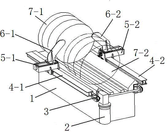
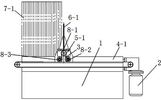
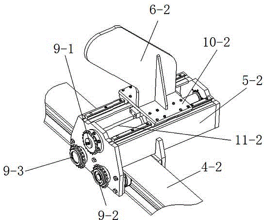
[0010] A coil stopper, comprising a frame, on which a transmission chain is arranged along the coil conveying direction, and a driving device for the transmission chain is provided, and the driving device is fixedly arranged on the frame, and a guide rail consistent with the direction of the chain is provided , the trolley is set on the guide rail, and the baffle is set on the trolley through the driving of the screw. The installation direction of the screw is perpendicular to the coil conveying direction, and the screw is connected to the trolley in rotation. The end of the sprocket is located at one end of the transmission chain. The main sprocket is driv...


PUM


Abstract

The invention discloses a material blocking device of a reel, and belongs to the technical field of steel machining equipment. The material blocking device comprises a rack, wherein the rack is provided with a conveying chain, a conveying chain driving device and guide rails along the reel conveying direction, the directions of the guide rails are consistent with the direction of the conveying chain, baffle trolleys are arranged on the guide rails, baffle plates are arranged on the baffle trolleys through screw rod driving devices, one end of each screw rod is fixedly connected with a main chain wheel, the main chain wheel is driven by the chain, the driving device drives the chain to rotate after materials are fed to the reel, the chain firstly drives the main chain wheel to rotate so as to drive the screw rods to rotate to drive the baffle plates, the main chain wheel cannot rotate any more after the baffle plates are driven in place, and the main chain wheel and the trolleys are used as a whole body under the driving of the rotation of the chain to drive the trolleys to move forwards together with the reel on the guide rails for realizing material blocking. According to the material blocking device disclosed by the invention, a set of independent driving systems is saved, and good benefit can be realized by being applied for material feeding and material blocking on the reel.

Description

technical field [0001] The invention relates to a material retaining device, in particular to a coil material retaining device, which belongs to the technical field of iron and steel processing equipment. Background technique [0002] Wire processing is one of the important varieties in the steel processing industry. During wire processing, it is often necessary to transport coils. In order to prevent deformation, winding, loose coils, etc. during coil transportation, a stopper device is required during coil transportation. , the stopper device needs to transport the front coil to the position under the positioning of the baffle and pull out the rear baffle, and then reset the stopper device to continue preparing for the next coil delivery, so the stopper device must have at least two-dimensional movement functions , in the traditional material blocking device, in order to realize the two-dimensional motion function, it is necessary to set up an independent drive device for ...

Claims


Application Information

Patent Timeline
IPC IPC(8): B65G47/24
Inventor 翟文翟武韩德丰许荣胜李小雨
Owner 湖南复星合力新材料有限公司
Learn More