
Pneumatic continuous feeding device

A technology of feeding device and cylinder, which is applied in the field of pneumatic continuous feeding device, can solve the problems of no-load feeding system, prone to jamming and jamming, etc., and achieve the effect of smooth feeding and increased reliability

Active Publication Date: 2017-01-25
NINGBO YONGBO MACHINERY MFG
View PDF5 Cites 0 Cited by
  • Summary
  • Abstract
  • Description
  • Claims
  • Application Information

AI Technical Summary

Problems solved by technology

[0004] The present invention provides a pneumatic continuous feeding device aiming at the disadvantage that the existing vibrating plate directly feeds the material and is prone to material jamming, which leads to the empty operation or jamming of the entire feeding system.

Method used


Image

  • Pneumatic continuous feeding device
  • Pneumatic continuous feeding device

Examples


Embodiment 1

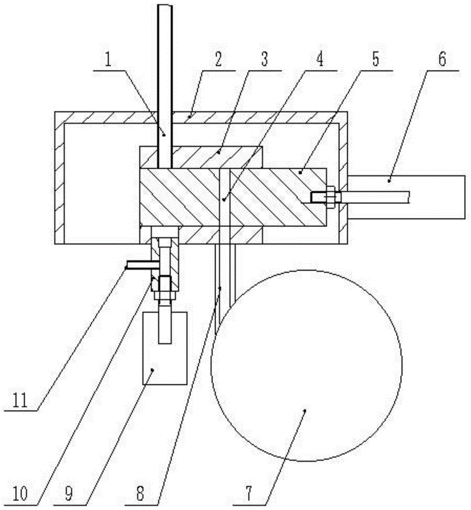
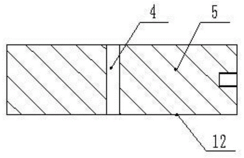
[0019] The pneumatic continuous feeding device, as shown in the accompanying drawings, includes a vibrating plate 7, a first pipe 10 connected to a high-pressure air source, and a slider 5 and a second pipe 1. The first pipe 10 can move along its axis, and the first pipe 10 can move along its axis. The axis of the first tube 10 coincides with the axis of the second tube 1, the slider 5 is provided with a through hole 4, the slider 5 can move so that the axis of the through hole 4 coincides with the axis of the first tube 10, and the slider 5 is close to the first tube Both sides 10 and 12 of the second tube 1 are plane. The side 12 of the slide block 5 acts as a material separator, isolating the rest of the blanks in the vibrating disk feedway 8 to ensure that the materials are taken one by one.

[0020] A hose 11 is radially connected to the first pipe 10, and the hose 11 is connected to a high-pressure air source. The first pipe 10 is provided with a first cylinder 9 on the ...


PUM


Abstract

The invention relates a conveying device, and discloses a pneumatic continuous conveying device. The pneumatic continuous conveying device comprises a vibration plate (7), a first pipeline (10) which is connected with a high pressure air source, a sliding block (5) and a second pipe (1); the first pipe (10) can move in the axis direction; the axis of the first pipe (10) is overlapped with the axis of the second pipe (1); a through hole (4) is formed in the sliding block (5); the sliding block (5) can move to enable the axis of the through hole (4) to be overlapped with the axis of the first pipe (10); two side surfaces (12) of the sliding block (5), close to the first pipe and the second pipe are both planes. According to the pneumatic continuous conveying device, long-distance conveying by a vibration plate is replaced by pneumatic conveying, so that the conveying is smooth, and meanwhile, the conveying reliability is improved.

Description

technical field [0001] The invention relates to a feeding device, in particular to a pneumatic continuous feeding device. Background technique [0002] The traditional vibrating plate feeding is prone to discharge blockage due to unqualified billets or blockage of iron filings. Then the subsequent feeding and production can only run without load. Especially in the case of long-distance feeding, as the material tube is too long and the number of blanks in the material tube increases, the vibration force is weakened, resulting in the phenomenon that the blank cannot be fed smoothly. If the material tube is directly connected to the subsequent feeding device, it is very likely that the billet will not be completely sent out of the material tube, and the subsequent feeding device will be stuck. [0003] The core of automatic feeding is the reliability when no one is there. Once the above two situations occur, the action of the automatic feeding mechanism will be meaningless. I...

Claims


Application Information

Patent Timeline
Patent Type & Authority Patents(China)
IPC IPC(8): B65G53/16B65G53/52B65G53/54B65G53/34B65G27/00
Inventor 王健柴挺飞
Owner NINGBO YONGBO MACHINERY MFG
Learn More