Deviation correcting device for elevator traction belt

A deviation correction device and elevator dragging technology, applied in the field of elevators, can solve problems such as manufacturing difficulties, shortened service life, and high cost, and achieve the effects of reducing manufacturing precision, reducing assembly difficulties, and saving manufacturing costs

Active Publication Date: 2017-08-25
GUANGZHOU GUANGRI ELEVATOR IND
View PDF10 Cites 0 Cited by
  • Summary
  • Abstract
  • Description
  • Claims
  • Application Information

AI Technical Summary

Problems solved by technology

There are also some designs that use multiple concave-convex surface belts, or multi-ribbed belts. Although they can effectively realize the limit guide of the traction belt, the structure is complex, the manufacture is difficult, and the cost is high. Due to the increase in the friction surface, the loss is also high, shortening belt life

Method used


Image

  • Deviation correcting device for elevator traction belt
  • Deviation correcting device for elevator traction belt
  • Deviation correcting device for elevator traction belt

Examples


Embodiment Construction

[0022] The present invention will be described in further detail below in conjunction with the accompanying drawings and specific examples, but the present invention is not limited to this specific example.

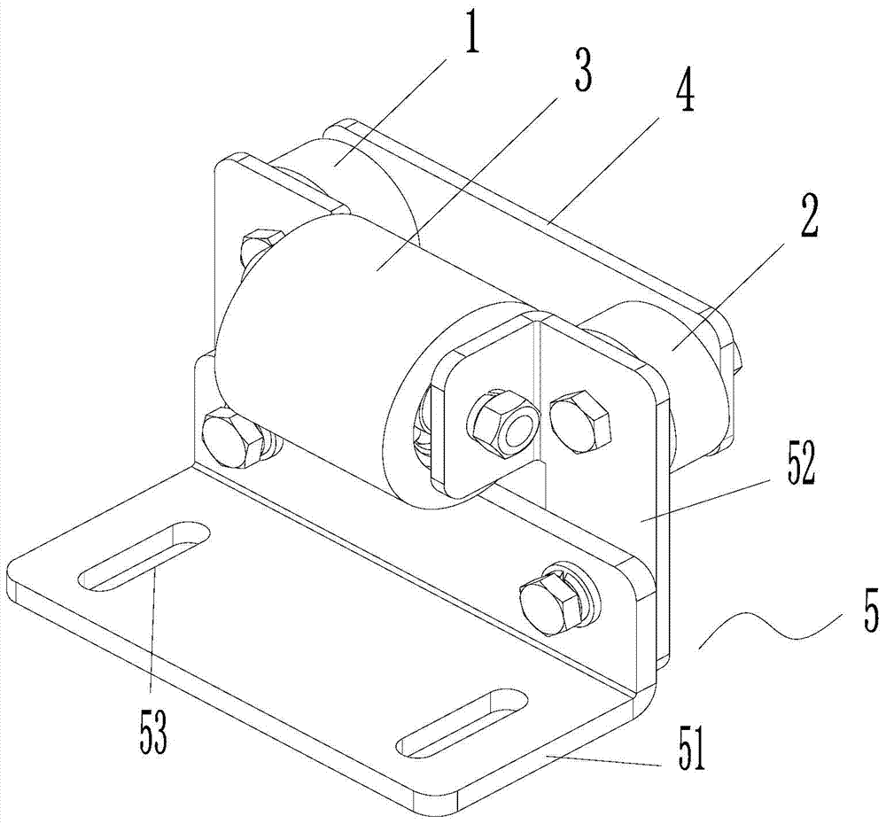
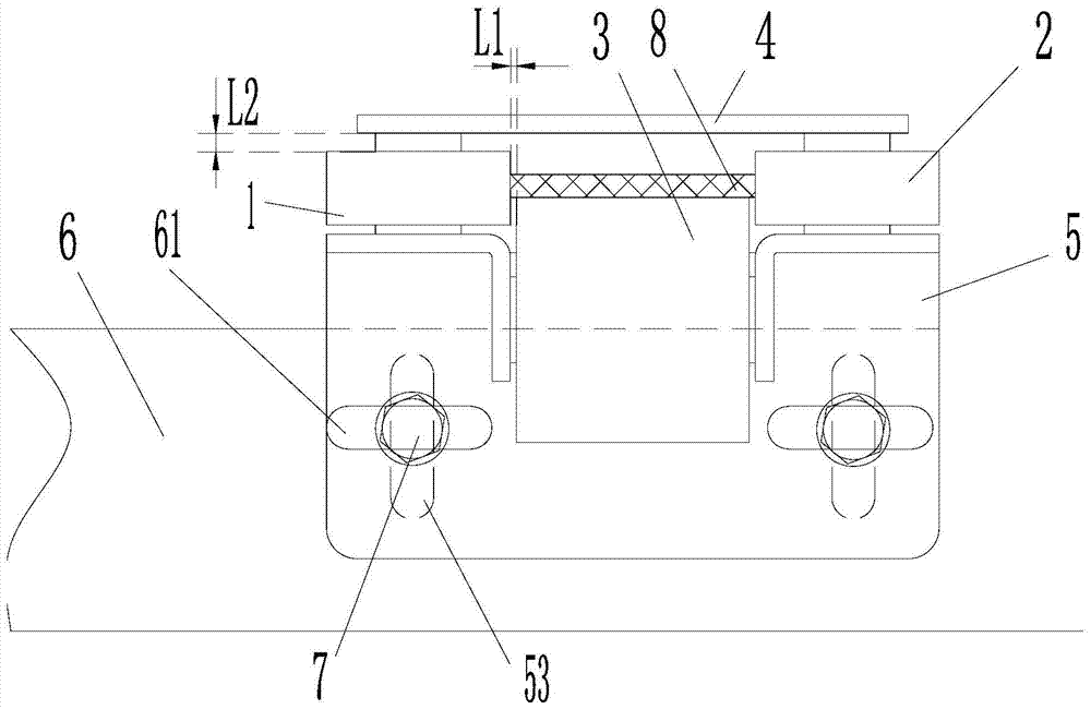
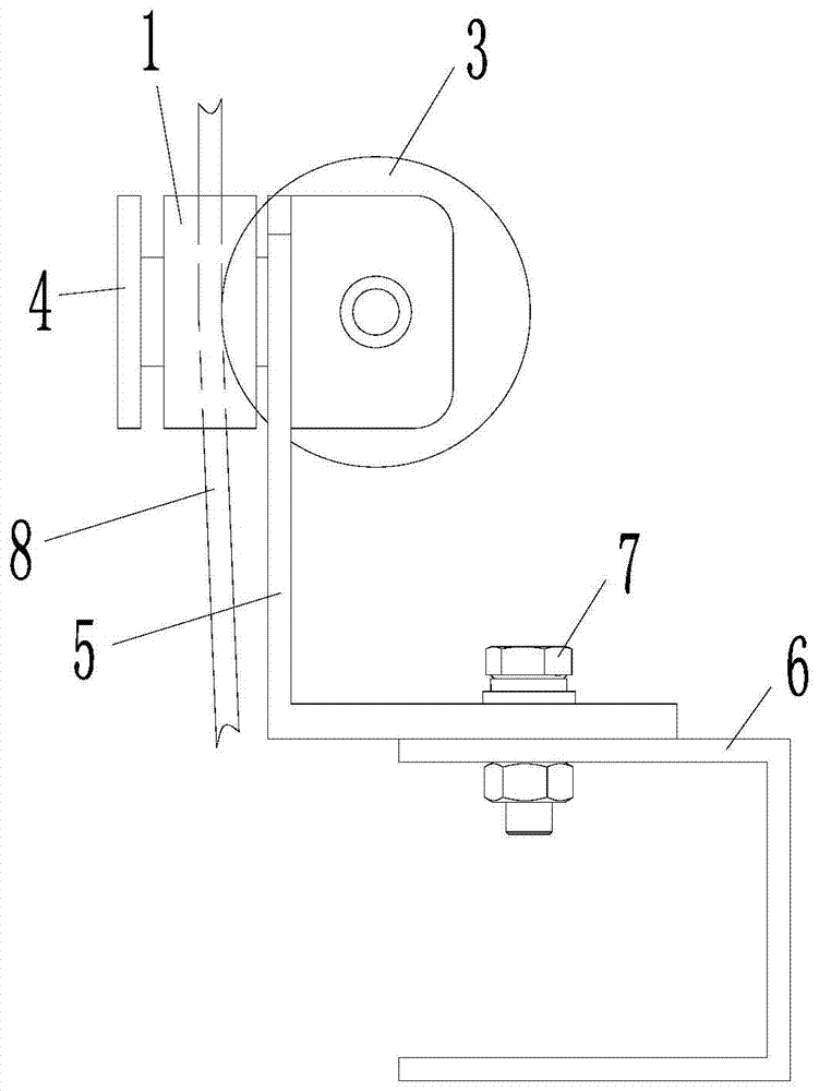
[0023] Such as Figure 1-Figure 3 As shown, a deviation correcting device for an elevator traction belt according to the present invention includes a baffle plate 4, a mounting seat 5, a bracket 6, a first roller 1, a second roller 2, and a pressing roller 3, etc.

[0024] The mounting seat 5 includes a bottom surface 51 and a mounting surface 52 perpendicular to the bottom surface 51 for mounting the rollers. In this embodiment, preferably, the position for installing the pinch roller 3 in the installation surface 52 adopts an elastic metal plate. After the pinch roller 3 is installed on it, the elevator traction belt 8 can be elastically compressed, allowing the traction During the operation of the leading belt 8, the pressing roller 3 is forced to produce a displaceme...


PUM


Abstract

The invention discloses a correcting device for an elevator traction belt. The device is characterized by comprising a mounting seat, a first roller, a second roller and a compressing roller; the first roller, the second roller and the compressing roller are arranged on the mounting seat; the outer round surfaces of the first roller and the second roller, at two sides of a traction belt to be corrected are limited to offset in the width direction; the positions of the outer round surfaces of the compressing roller, close to the surface of the traction belt to be corrected apply a pressure in the thickness direction. With the adoption of the correcting device for the elevator traction belt, the offset of the traction belt in running can be corrected, the verticality of the traction belt moving in and out of a belt pulley and a pulley axis is ensured, and the traction belt is prevented from being offset and damaged.

Description

technical field [0001] The invention relates to the field of elevators, in particular to a deviation correcting device for elevator traction belts. Background technique [0002] Traditional elevators use steel wire ropes as suspension and traction components. According to standard requirements, the diameter of the traction wheel and guide wheel must be 40 times the diameter of the steel wire rope. Generally, 10mm steel wire rope is used, so the diameter of the traction wheel and guide wheel is generally 400mm, or even larger. As a result, the main body of the elevator has a large volume, which is inconvenient to carry, consumes a large amount of metal materials and requires more civil engineering space to accommodate. [0003] In order to reduce the size of the main engine, a new technology uses flat elevator traction belts as suspension components, such as composite steel belts and carbon fiber belts, etc., wherein the composite steel belts are made of steel wire ropes wit...

Claims


Application Information

Patent Timeline
Patent Type & Authority Patents(China)
IPC IPC(8): B66B7/02
CPCB66B7/062
Inventor 李密贺云朗侯应浩
Owner GUANGZHOU GUANGRI ELEVATOR IND
Why Eureka
Try Eureka