Supercharge Your Innovation With Domain-Expert AI Agents!

Overlapping type rainwater collecting device

A rain collector and layered technology, applied in the field of combined rainwater collection devices, can solve the problems of small watering amount, artificial or diverted watering, etc., and achieve the effects of simple structure, convenient use, and expansion of rainwater collection efficiency.

Inactive Publication Date: 2015-04-29
ZHEJIANG UNIVERSITY OF SCIENCE AND TECHNOLOGY +1
View PDF6 Cites 1 Cited by
  • Summary
  • Abstract
  • Description
  • Claims
  • Application Information

AI Technical Summary

Problems solved by technology

[0003] However, we found that there is room for a large amount of rainwater collection in a limited space. For example, the greening at the bottom of some viaducts cannot be directly watered by rainwater, and artificial or water diversion watering is completely required.
If rainwater is collected and irrigated on the upper side of the viaduct, a lot of labor and tap water can be saved, but when the problem arises, the area available for rain collection on the viaduct is very limited. If a traditional rainwater collector is used, the amount of irrigation is very small of

Method used


Image

  • Overlapping type rainwater collecting device
  • Overlapping type rainwater collecting device
  • Overlapping type rainwater collecting device

Examples


Embodiment 1

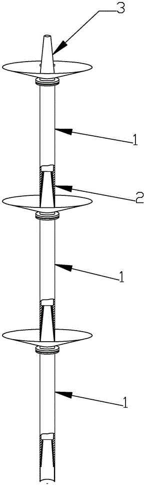
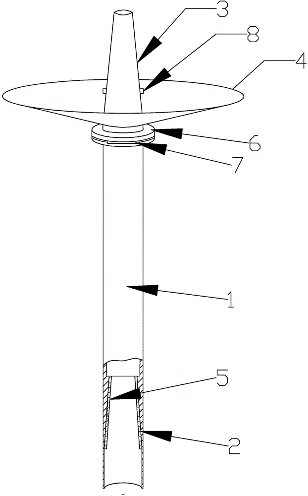
[0018] Such as figure 1 , figure 2 , image 3 As shown, the present invention is a laminated rain collector, which includes 3 longitudinal branch pipes, the longitudinal branch pipes include a main pipe 1, a top pipe 3 is provided at the upper end of the main pipe, a tail pipe 2 is provided at the lower end of the main pipe, and the upper part of the main pipe 1 A rainwater collection tank 4 with a conical structure is provided, and the main pipe is provided with a rainwater inlet hole at the bottom of the rainwater collection tank 4, and the outer wall of the jacking pipe and the inner hole of the tail pipe have mutually adapted dimensions, and the outer wall of the jacking pipe is Tapered structure, the inner hole of the tail pipe includes a sealing ring 5 that is compatible with the outer wall of the top pipe, and the longitudinal branch pipes are sequentially connected from head to tail through the mutual socket of the top pipe and the tail pipe. The lower part of the j...

Embodiment 2

[0021] Such as Figure 4 As shown, on the basis of Embodiment 1, this embodiment adds the following technical features, the upper edge of one side of the rainwater collection tank is provided with a rain collecting baffle 9 . Since most of the rainwater falls at an incline, if the vertical branch pipe is rotated according to the wind direction and the rain-collecting baffle is adjusted so that the inside of the rain-collecting baffle is the windward side, the largest amount of rainwater can be blocked on the rain-collecting baffle. It will flow into the rainwater collection tank, which greatly improves the rainwater collection efficiency. In actual use, the rain collecting baffle can be adjusted seasonally according to the common wind direction of the season.


PUM


Abstract

The invention relates to an overlapping type rainwater collecting device, which comprises a plurality of longitudinal branch pipes, wherein each longitudinal branch pipe comprises a main pipe, a top pipe is arranged at the upper end of each main pipe, a tail pipe is arranged at the lower end of each main pipe, an annular rainwater collecting groove is formed in the upper part of each main pipe, a rainwater inlet hole is formed in the bottom part of the rainwater collecting groove of each main pipe, the outer wall of each top pipe and the inner hole of the corresponding tail pipe are matched in sizes, and the longitudinal branch pipes are sequentially connected in a head-to-tail way through the mutual sleeving of the corresponding top pipe and the corresponding tail pipe. The overlapping type rainwater collecting device has the characteristics that the structure is simple, the convenience in use is realized, the reasonable combination is realized according to the requirements, the requirement on floor area is lower, the rainwater collecting efficiency can be greatly improved, and the like.

Description

technical field [0001] The invention relates to a rainwater collection device, in particular to a combined rainwater collection device. Background technique [0002] Rainwater harvesting device is a very common equipment in arid areas, but with the development of modern society, the applicable range and application fields of rainwater harvesting device are constantly expanding. In order to expand the amount of rainwater collected, the current rainwater collection devices need to expand the lateral area of ​​the rainwater collection part as much as possible, but the expansion of this area is limited, especially in some facilities with small spaces. The efficiency of rainwater harvesting will be very limited, and as far as existing rainwater harvesting devices are concerned, there will be no ability to expand the efficiency of rainwater harvesting. [0003] However, we found that there is room for application of a relatively large amount of rainwater collection in a limited...

Claims


Application Information

Patent Timeline
Patent Type & Authority Applications(China)
IPC IPC(8): E03B3/02
CPCY02A20/108E03B3/02
Inventor 陈宁章道华徐兴翁卫兵项冰静
Owner ZHEJIANG UNIVERSITY OF SCIENCE AND TECHNOLOGY
Features
  • R&D
  • Intellectual Property
  • Life Sciences
  • Materials
  • Tech Scout
  • Unparalleled Data Quality
  • Higher Quality Content
  • 60% Fewer Hallucinations
Learn More