Mounting structure for suspension device

A technology of suspension device and installation structure, applied in the direction of connecting components, pins, mechanical equipment, etc., can solve the problems of skew and easy falling of expansion screws, and achieve the effect of convenient installation and prevention of skew.

Active Publication Date: 2015-04-29
PUTIAN INTELLIGENT LIGHTING INST +1
View PDF6 Cites 5 Cited by
  • Summary
  • Abstract
  • Description
  • Claims
  • Application Information

AI Technical Summary

Problems solved by technology

[0004] The technical problem solved by the present invention is to provide an installation structure of the suspension device, which solves the problem that the expansion screw is easy to fall and skew during the installation process

Method used


Image

  • Mounting structure for suspension device
  • Mounting structure for suspension device
  • Mounting structure for suspension device

Examples


Embodiment 1

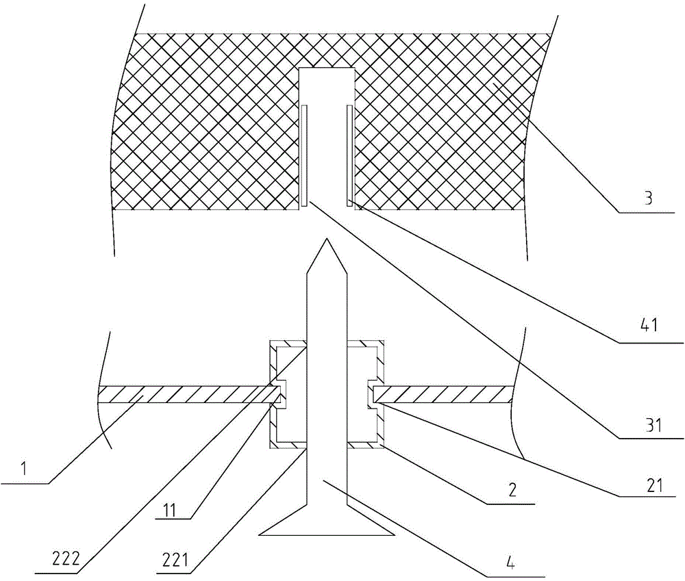
[0026] refer to figure 1 , shows a mounting structure for a suspension device, including a base plate 1 and a threaded fixture 4, on which electrical appliances or wall lamps and other items are installed, and a mounting hole 11 is provided on the base plate 1, and the threaded fixture 4 passes through the mounting hole 11. Fix the base plate 1 on the installation plane 3. In the present invention, a guide sleeve 2 is installed on the base plate 1. The guide sleeve 2 is provided with a positioning hole for the positioning screw fixture 4, and the positioning hole corresponds to the installation hole 11. The threaded fixing member 4 is connected to the installation plane 3 through the positioning hole. Position the threaded fixing part 4 through the guide sleeve 2, prevent the threaded fixing part 4 from deflecting during the installation process, and prevent the threaded fixing part 4 from being skewed and cannot be accurately installed on the installation plane 3; and the gui...

Embodiment 2

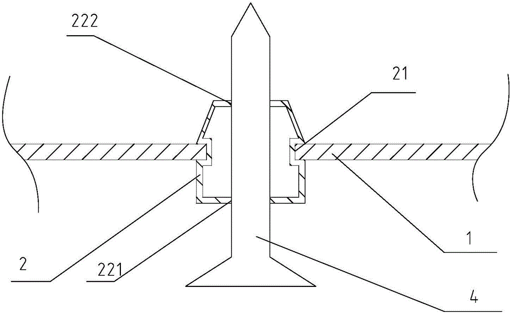
[0036] refer to Figure 4 , shows a mounting structure for a suspension device, including a base plate 1 and a threaded fixture 4, on which electrical appliances or wall lamps and other components are installed, and a mounting hole 11 is provided on the base plate 1, and a guide sleeve is connected to the mounting hole 11 2. The guide sleeve 2 is provided with a positioning hole 22 for locating the threaded fastener 4 , the axial direction of the positioning hole 22 corresponds to the axial direction of the installation hole 11 , and the threaded fastener 4 passes through the positioning hole 22 to connect to the installation plane 3 .

[0037] In the reference example 1 figure 1 , wherein the threaded fixing part 4 is an expansion screw, and the bore 31 is provided with an expansion sleeve 41, and the expansion screw is connected to the expansion sleeve 41, and the expansion screw can be a stainless steel expansion screw or a plastic expansion screw.

[0038] refer to Figu...


PUM


Abstract

The invention discloses a mounting structure for a suspension device and belongs to the field of suspension mounting. The technical problem that the mounting quality and progress are influenced by the easily generating deflection and falling of the bolt when the present suspension device is mounted is solved. The mounting structure for the suspension device provided by the invention comprises a base plate and a thread fastener, wherein a mounting hole is formed in the base plate; the thread fastener passes through the mounting hole so as to mount the base plate on a mounting plane; the mounting structure for the suspension device further comprises a guide sleeve; the guide sleeve is mounted on the base plate; a positioning hole used for positioning the thread fastener is formed in the guide sleeve; the positioning hole is corresponding to the mounting hole. The mounting structure for the suspension device is used for hanging the articles, such as, lamps, wall-mounted parts, decorative materials, wall-absorbing ceiling furniture on a wall.

Description

【Technical field】 [0001] The invention relates to an installation structure of a suspension device, in particular to an installation structure for objects suspended on a wall. 【Background technique】 [0002] In order to utilize the indoor space, many items need to be installed on the installation planes such as walls and ceilings; these items include lamps, wall hangings, decorative materials, wall-absorbing and ceiling furniture, etc. The commonly used and relatively stable installation method in the field of installation is the expansion screw connection. The expansion screw connection includes stainless steel expansion screws and plastic expansion screws. Fastening on other materials belongs to the application with high mechanical strength; the mechanical strength that plastic expansion screws can withstand is relatively small, and the force range of plastic expansion screws can meet the fixed needs of lamps, murals, decorative furniture and other objects. The installati...

Claims


Application Information

Patent Timeline
Patent Type & Authority Applications(China)
IPC IPC(8): F16B13/06F16B13/04
CPCF16B13/04F16B13/065
Inventor 方溁田开云徐耀增
Owner PUTIAN INTELLIGENT LIGHTING INST
Why Eureka
Try Eureka