
Electromagnetic valve

A technology of solenoid valve and valve body, applied in the direction of electromagnet, magnet, electromagnet with armature, etc., can solve the problems of increasing energy consumption, affecting the electromagnetic attraction force of stator and piston, increasing the supply current of winding, etc., so as to increase the electromagnetic attraction force Effect

Active Publication Date: 2015-04-29
德昌医疗科技(深圳)有限公司
View PDF4 Cites 4 Cited by
  • Summary
  • Abstract
  • Description
  • Claims
  • Application Information

AI Technical Summary

Problems solved by technology

In this way, there is a large air gap between the outer surface of the piston and the magnetizer, resulting in a large magnetic resistance, thereby affecting the electromagnetic attraction between the stator and the piston
In practice, in order to ensure that the suction force between the stator and the piston is sufficient when the winding is energized, the supply current of the winding has to be increased, thereby increasing energy consumption
Moreover, in the above solenoid valve, the position between the valve body and the electromagnet is relatively fixed, so its application is limited

Method used


Image

  • Electromagnetic valve
  • Electromagnetic valve
  • Electromagnetic valve

Examples


Embodiment Construction

[0043] The technical solutions and other beneficial effects of the present invention will be apparent through the detailed description of specific embodiments of the present invention below in conjunction with the accompanying drawings. The drawings are provided for reference and illustration only, and are not intended to limit the present invention. The dimensions shown in the drawings are only for the convenience of clear description, and do not limit the proportional relationship.

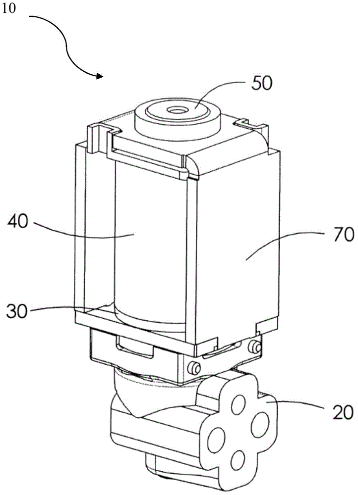
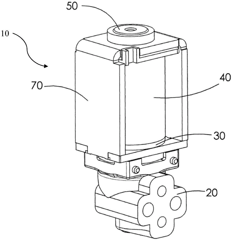
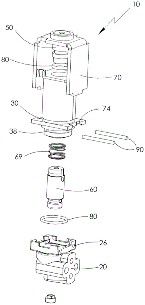
[0044] Please refer to Figure 1 to Image 6 , The solenoid valve 10 in a preferred embodiment of the present invention includes a valve body 20 , a bobbin 30 , a winding 40 , a stator 50 , a movable member 60 and a magnetic circuit mechanism 70 .

[0045] The valve body 20 is preferably made of plastic and includes several channels. In this embodiment, the valve body 20 includes a pair of first passages 22 and a pair of second passages 24. In the valve body, the first passages 22 communicate w...


PUM


Abstract

A solenoid valve has a valve body with first and second ports. A bobbin is mounted to the valve body. A winding is wound on the bobbin. A stator is fitted to one end of a hole through the bobbin and defines a third port therein. A plunger is slidably fitted to the hole and movable between a normal position and an energized position. Two plugs are installed at respective ends of the plunger and arranged to selectively close the first and third ports. A flux return device is fixed to the stator and the bobbin. A spring returns the plunger from the energized position, where the plunger closes the third port and the first and second ports communicate with each other via the hole in the bobbin, to the normal position, where the plunger closes the first port and the second and third ports communicate with each.

Description

technical field [0001] The invention relates to a solenoid valve. Background technique [0002] Solenoid valves have been widely used in medical equipment such as massage devices. U.S. Patent No. 5,992,461 discloses an existing solenoid valve. The solenoid valve includes a valve body and an electromagnet. The valve body is provided with two interfaces. The winding on the wire frame, the stator arranged at one end of the inner hole of the wire frame and the hollow piston arranged at the other end of the inner hole of the wire frame, the stator is provided with a third interface, a pair of plugs and an inner hole between the plugs are arranged in the piston spring. An outer spring is arranged between the piston and the stator. When the winding is energized, the piston is magnetized and attracted by the suction force of the stator, the plug at the end of the piston closes the third port on the stator, and the two ports on the valve body communicate with each other. After th...

Claims


Application Information

Patent Timeline
Patent Type & Authority Applications(China)
IPC IPC(8): F16K31/06
CPCF16K31/0675H01F7/121H01F7/126H01F7/1607H01F2007/083F16K31/0606F16K31/0627F16K31/02H01F7/16
Inventor 亨利克·斯文森汤玛仕·瑞世轲
Owner 德昌医疗科技(深圳)有限公司
Learn More