
Novel composite proportional electromagnet

A proportional electromagnet, a new type of technology, applied in the field of electromagnets, can solve the problems of air reluctance and flux leakage increase, non-working air gap increase, magnetic energy utilization rate reduction, etc., to reduce air reluctance and flux leakage, Reduce the radial gap and increase the effect of electromagnetic attraction

Active Publication Date: 2017-07-07
HUAWEI TEHCHNOLOGIES CO LTD
View PDF6 Cites 1 Cited by
  • Summary
  • Abstract
  • Description
  • Claims
  • Application Information

AI Technical Summary

Problems solved by technology

The force of the existing proportional electromagnet at a certain voltage or current is generally constant and cannot be adjusted. If the working condition changes, it will take a lot of time to readjust so that the proportional solenoid can re-proportionately control the new working condition.
[0004] In addition, the end face of the traditional armature is generally flat. When the armature moves, the non-working air gap between the armature and the end cover pole shoe increases, the air reluctance and magnetic leakage increase, the electromagnetic force generated by the magnetic flux becomes smaller, and the utilization of magnetic energy rate reduction

Method used


Image

  • Novel composite proportional electromagnet
  • Novel composite proportional electromagnet
  • Novel composite proportional electromagnet

Examples


Embodiment Construction

[0034] In order to facilitate the understanding of the present invention, the present invention will be described in more detail below in conjunction with the accompanying drawings and specific embodiments. Preferred embodiments of the invention are shown in the accompanying drawings. However, the present invention can be implemented in many different forms and is not limited to the embodiments described in this specification. On the contrary, these embodiments are provided to make the understanding of the disclosure of the present invention more thorough and comprehensive.

[0035] It should be noted that when an element is referred to as being “fixed” to another element, it can be directly on the other element or there can also be an intervening element. When an element is referred to as being "connected to" another element, it can be directly connected to the other element or intervening elements may also be present. The terms "vertical", "horizontal", "left", "right" and...


PUM


Abstract

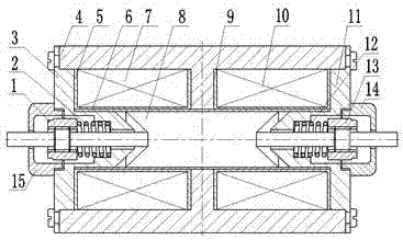
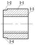
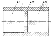
The invention discloses a novel composite proportional electromagnet comprising a shell, a magnetic isolating ring, an armature, a left cover plate, a left pressure regulating nut, a right cover plate and a right pressure adjusting nut, wherein the magnetic isolating ring is sheathed in the shell; the armature is located in the magnetic isolating ring; the left pressure regulating nut is connected to a right end of the armature; the left cover plate is fixed on a left end of the shell; the right pressure adjusting nut is connected to the right end of the armature; and the right cover plate is fixed on the right end of the shell. According to the novel composite proportional electromagnet disclosed by the invention, the traditional magnetic isolating ring structure is replaced by a thin-walled structure, thereby simplifying the system structure, reducing the processing procedures and improving the production efficiency; the end face of the armature is changed to improve the electromagnetic attraction and improve the output force characteristics; and the pre-tightening forces acting on the two ends of the armature can be conveniently adjusted through pressure regulating springs to realize the adjustability of the acting force of the proportional electromagnet at a certain voltage or current. The novel composite proportional electromagnet disclosed by the invention is simple in structure, convenient to use and excellent in performance, can realize bidirectional displacement output, and can be directly connected with a valve core of a slide valve so as to control the bidirectional position proportion of the valve core of the slide valve.

Description

technical field [0001] The invention relates to the technical field of electromagnets, in particular to a proportional electromagnet which adopts a new magnetic isolation ring structure, conveniently adjusts the pretightening force acting on both ends of an armature, and increases the electromagnetic output force. Background technique [0002] The proportional electromagnet is an electric-mechanical conversion device of the electro-hydraulic proportional control element. Its function is to convert the current or voltage signal output by the proportional control amplifier into force or displacement in proportion. The electro-hydraulic proportional control system has a very important influence. The traditional proportional electromagnet structure generally includes a coil, a shell, an armature, and a magnetic isolation ring. For example, patent DE3309904 discloses a proportional electromagnet. The magnetic isolation ring is made of brass, a non-magnetic material. It needs to ...

Claims


Application Information

Patent Timeline
Patent Type & Authority Applications(China)
IPC IPC(8): H01F7/08H01F7/129H01F7/16
CPCH01F7/08H01F7/129H01F7/1607H01F2007/086H01F2007/163
Inventor 胡万强刘国红姚宁
Owner HUAWEI TEHCHNOLOGIES CO LTD
Learn More