Pilot valve assembly

A pilot valve and component technology, applied in the field of solenoid valves, can solve the problems of static iron core absorption, high cost, difficult to return, etc., to achieve the effect of smaller wire diameter, lower cost, and avoid complex structure

Pending Publication Date: 2018-11-23
NINGBO FEITAI IND AUTOMATION EQUIP
View PDF5 Cites 1 Cited by
  • Summary
  • Abstract
  • Description
  • Claims
  • Application Information

AI Technical Summary

Problems solved by technology

However, since the coil frame around which the enameled wire is wound has a cylindrical shape, but its shell is rectangular, the space occupied by the coil frame in the rectangular chamber is small, and therefore, in order to achieve the required magnetic flux, it is necessary to use The thicker enameled wire is wound on the bobbin to complete, so the cost is high
[0003] The end faces of the static iron core and the first moving iron core are smooth, and sometimes the air flow will bring moisture, which will cause the dynamic and static iron cores to absorb after the accumulation of moisture, making it difficult to return

Method used


Image

  • Pilot valve assembly
  • Pilot valve assembly
  • Pilot valve assembly

Examples


Embodiment 1

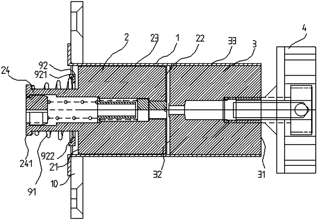
[0046] In this embodiment, the pilot valve assembly includes a sleeve structure 1 , a first moving iron core 2 , an elastic device (not shown), a static iron core 3 and a fixing device 4 . The above-mentioned components are mainly introduced below.

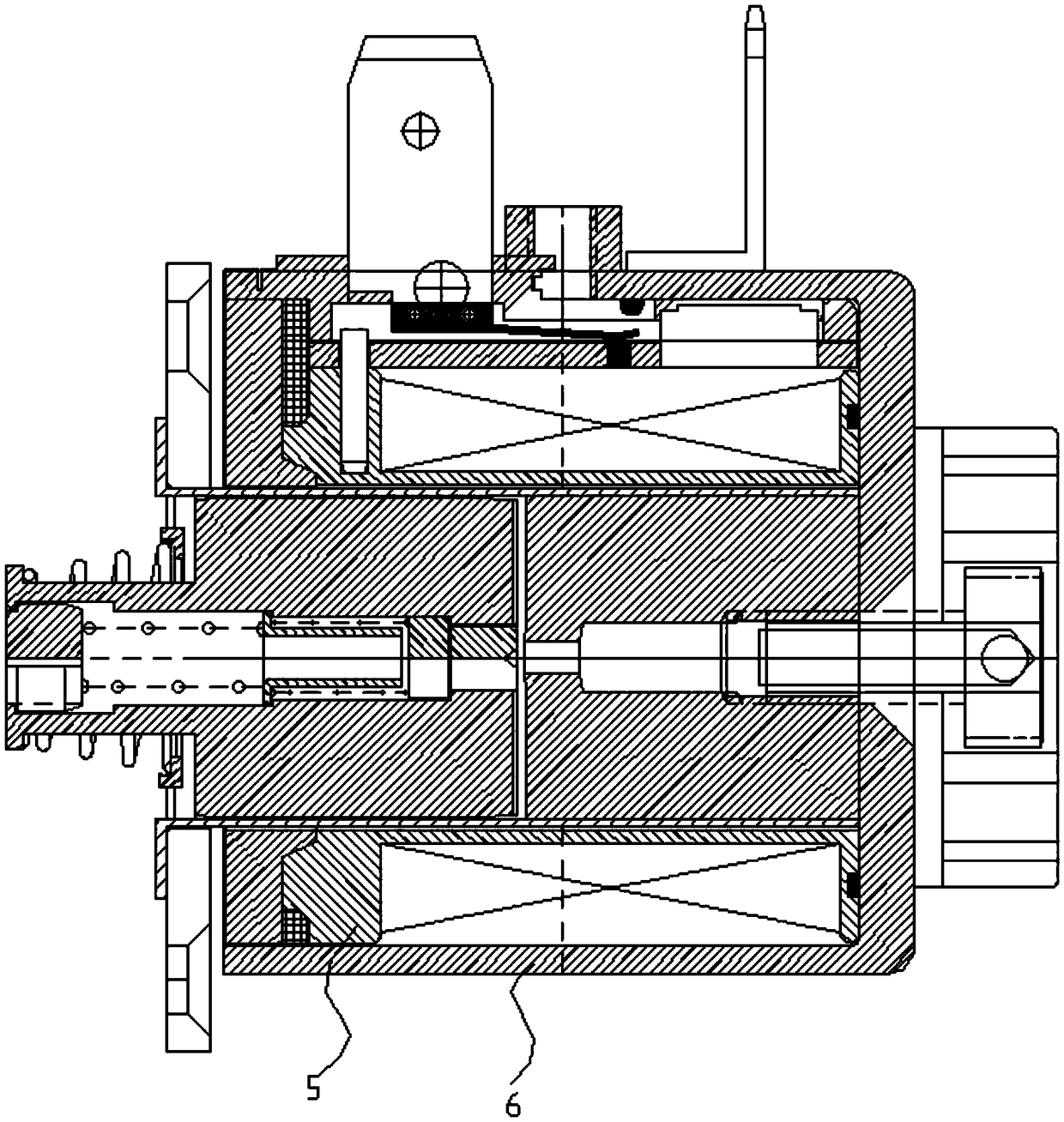
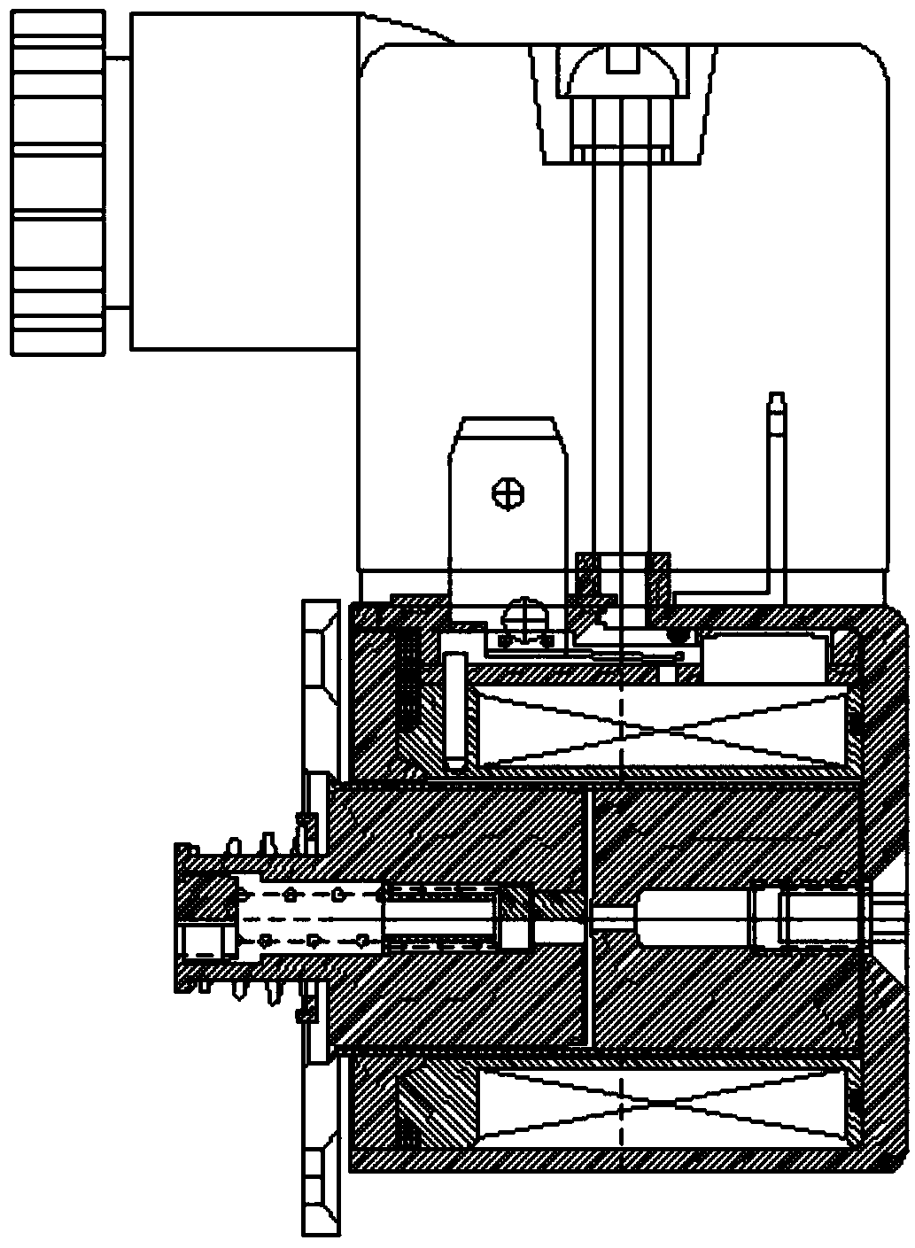
[0047] For details, please refer to Figure 1 to Figure 2 , Figure 12 to Figure 13 , figure 1 It is a schematic cross-sectional structure diagram of a pilot valve assembly in Embodiment 1 of the present invention; figure 2 It is a schematic cross-sectional structure diagram of a solenoid valve composed of a pilot valve assembly in Embodiment 1 of the present invention; Figure 12 It is a schematic diagram of a horizontal cross-sectional structure of the first structure of the sleeve structure of a pilot valve assembly in the present invention; Figure 13 It is a schematic cross-sectional structural schematic diagram of a vertical section of the first structure of a sleeve structure of a pilot valve assembly in the present in...

Embodiment 2

[0053] In this embodiment, the pilot valve assembly includes a sleeve structure 1 , a first moving iron core 2 , an elastic device (not shown), a static iron core 3 , a second moving iron core 7 , a fixing block 74 and a fixing device 4 . The above-mentioned components are mainly introduced below.

[0054] For details, please refer to Figure 10 to Figure 13 , Figure 10 It is a schematic cross-sectional structure diagram of a pilot valve assembly in Embodiment 2 of the present invention; Figure 11 It is a schematic cross-sectional structure diagram of a solenoid valve composed of a pilot valve assembly in Embodiment 2 of the present invention; Figure 12 It is a schematic diagram of a horizontal cross-sectional structure of the first structure of the sleeve structure of a pilot valve assembly in the present invention; Figure 13 It is a schematic cross-sectional structural schematic diagram of a vertical section of the first structure of a sleeve structure of a pilot valv...


PUM


Abstract

The invention provides a pilot valve assembly. The pilot valve assembly comprises a sleeve structure, a first movable iron core, an elastic device, a static iron core and a fixing device, wherein thesleeve structure is of a hollow cuboid structure, and the sleeve structure is arranged in an inner cavity of a coil framework; the first movable iron core is of a cuboid structure, and the first movable iron core is provided with a first surface, a second surface and a first side surface; the first movable iron core is inserted into the hollow cuboid structure, a guide head is arranged on the first surface, the elastic device sleeves the guide head, and the static iron core is of a cuboid structure; the static iron core is provided with a third surface, a fourth surface and a second side surface, and the static iron core is arranged in the hollow cuboid structure; the fixing device is arranged on the third surface, and the iron cores are fixedly connected with a shell through the fixing device. According to the pilot valve assembly, the sleeve structure is changed from a circular shape to a rectangular shape, and electromagnetic force is increased; an electromagnetic valve using the pilot valve assembly can save energy by 20-70%, the wire diameter under the same power is reduced, and the cost is reduced; the pilot valve assembly is easy to process; the movable iron core and the static iron core are not likely to attract each other.

Description

technical field [0001] The invention relates to the technical field of solenoid valves, in particular to a pilot valve assembly. Background technique [0002] At present, electromagnetic relays have been widely used in household appliances, automobiles, etc. With the development of technology, there are more and more types, and the internal coil frame is an indispensable part of each electromagnetic relay. The existing solenoid valve includes a main valve body part and a control part. The control part includes a coil combination, a terminal block, a junction box and a pilot valve push rod which are installed in the casing, and the terminal block is arranged on the casing. The junction box Sleeved on the outside of the terminal block, there are electrical components connected to the inserts, and the external wiring is connected to the electrical components after passing through the junction box. When the solenoid valve is electrified, the coil in the casing has current, and ...

Claims


Application Information

Patent Timeline
Patent Type & Authority Applications(China)
IPC IPC(8): F16K31/06
CPCF16K31/0675
Inventor 皇甫美蓉皇甫炳
Owner NINGBO FEITAI IND AUTOMATION EQUIP
Why Eureka
Try Eureka