
Air Conditioning System

An air-conditioning system and branch pipe technology, which is applied in the field of air-conditioning, can solve problems such as large resistance, unsmooth liquid supply, and inability to carry gaseous refrigerants, etc., to achieve the effect of improving service life and ensuring reliable operation

Active Publication Date: 2017-06-06
GREE ELECTRIC APPLIANCES INC
View PDF6 Cites 0 Cited by
  • Summary
  • Abstract
  • Description
  • Claims
  • Application Information

AI Technical Summary

Problems solved by technology

[0003] However, in order to make the air-conditioning system work normally, the refrigerant contains lubricating oil. Since the displacement of the air-conditioning system at full load and partial load is quite different, the flow rate of the gaseous refrigerant entering the compressor 1' is also quite different. Therefore, , when the air-conditioning system is working at low load, the gaseous refrigerant cannot carry sufficient lubrication into the compressor 1′ because the flow rate of the gaseous refrigerant is too small, which reduces the service life of the compressor 1′
In some air-conditioning systems, the intake pipe 2' connected to the air inlet of the compressor 1' is relatively long, and the resistance of gas flow in the air intake pipe 2' is relatively large, and the air intake pipe 2' is at the air inlet of the compressor 1' The resulting pressure drop is relatively large, which further causes the gaseous refrigerant to fail to carry enough lubricating oil into the compressor 1', further reducing the service life of the compressor 1'
In addition, based on the large difference between the full load and partial load of the air conditioning system, the flow rate of the liquid refrigerant flowing from the liquid storage tank 3' to the condenser through the liquid inlet pipe 4' is unstable, which in turn leads to unsmooth liquid supply and affects Normal operation of the air conditioning system

Method used


Image

  • Air Conditioning System
  • Air Conditioning System

Examples


Embodiment 1

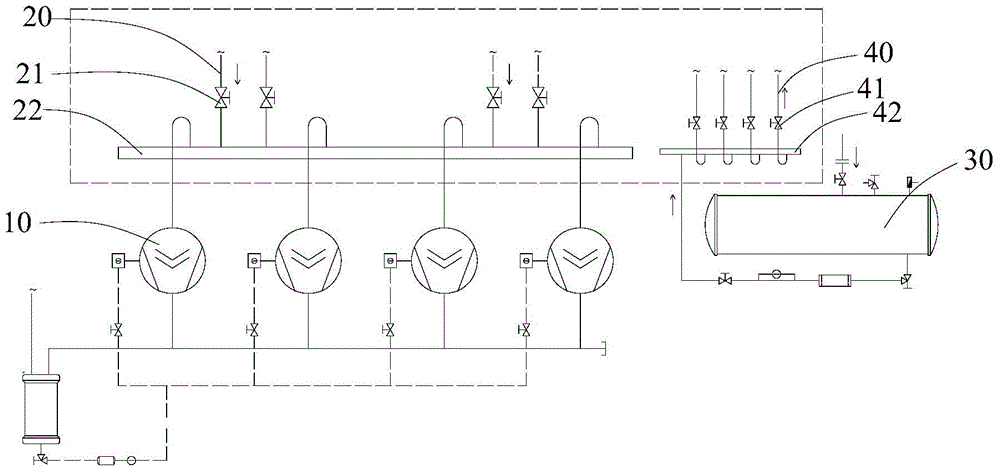
[0037] The air conditioning system of the first embodiment further includes a gas-liquid separator (not shown in the figure), which is located between the compressor 10 and each suction branch pipe 20, and the gas-liquid separator is connected to the compressor 10 and each suction branch respectively The branch pipes 20 are connected. In this way, the liquid refrigerant can be prevented from flowing into the compressor 10, and further, a gas-liquid separator is located between the compressor 10 and the suction manifold 22, wherein the suction manifold has the effect of uniform liquid separation.

Embodiment 2

[0038] The difference between the air conditioning system (not shown) of the second embodiment and the first embodiment is that, in the second embodiment, a gas-liquid separator is used to replace the suction manifold 22 in the air conditioning system of the first embodiment. Each suction branch pipe 20 has an intake end and an exhaust end. The exhaust end of each suction branch pipe 20 is connected to the gas-liquid separator, and the exhaust branch pipe of the gas-liquid separator is connected to the intake port of the compressor 10 one by one. Correspondingly communicate. Among them, the gas-liquid separator is a horizontal gas-liquid separator, which has the functions of uniform liquid separation and gas-liquid separation.

Embodiment 3

[0039] The difference between the air conditioning system (not shown) of the third embodiment and the first embodiment is that in the third embodiment, there is only one compressor 10, and the compressor 10 can also achieve full load operation and partial load operation. The air conditioning system of the third embodiment can also increase the service life of the compressor.


PUM


Abstract

The invention provides an air-conditioning system, comprising: a compressor (10) having an air inlet and an air outlet; end and exhaust end, the exhaust end of each suction branch pipe (20) is connected with the air inlet of the compressor (10); the suction main pipe (22) is located between the compressor (10) and each suction branch pipe (20) ), the main suction pipe (22) communicates with the compressor (10) and each suction branch pipe (20) respectively. The air conditioning system of the invention improves the service life of the compressor.

Description

Technical field [0001] The present invention relates to the technical field of air conditioning, and in particular to an air conditioning system. Background technique [0002] At present, the working process of the air conditioning system is mainly as follows: figure 1 As shown, the compressor 1'compresses the low-temperature and low-pressure gaseous refrigerant entering it into a high-temperature and high-pressure gaseous refrigerant, and then the refrigerant flows into the condenser to form a liquid refrigerant under the action of the condenser. The agent flows into the evaporator and forms a low-temperature and low-pressure gaseous refrigerant under the action of the evaporator, and then flows into the compressor 1'through the intake pipe 2'for compression. In order to prevent liquid refrigerant from flowing into the compressor 1', a liquid separator is provided between the compressor 1'and the evaporator. For central air conditioners that require a lot of refrigerant, in ord...

Claims


Application Information

Patent Timeline
Patent Type & Authority Patents(China)
IPC IPC(8): F25B41/00F25B43/00F25B41/40
CPCF25B1/00F25B31/00F25B43/006F25B41/40
Inventor 吴家威张宁李金奎齐方成谢斌斌熊凯
Owner GREE ELECTRIC APPLIANCES INC
Learn More