

Metering box for power distribution network
A metering box and distribution network technology, applied in the field of metering boxes, can solve problems such as unreasonable structure of metering boxes, inconvenient installation and operation, etc., and achieve the effects of convenient installation or maintenance, convenient operation, and convenient use
- Summary
- Abstract
- Description
- Claims
- Application Information
AI Technical Summary
Problems solved by technology
Method used
Image

Examples
Embodiment Construction
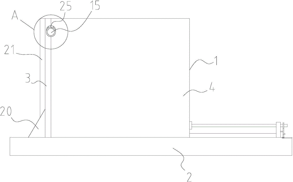
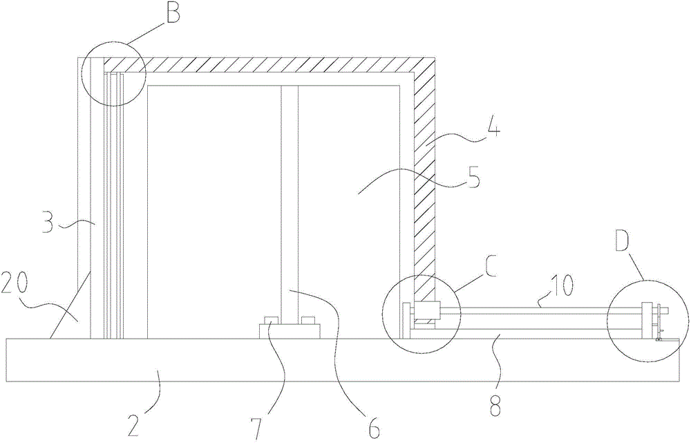
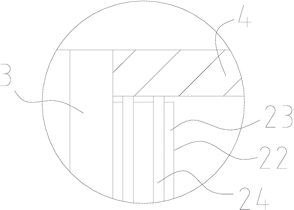
[0018] The metering box for distribution network of the present invention will be further described below in conjunction with the accompanying drawings. Such as figure 1 , figure 2 , image 3 , Figure 4 , Figure 5 , Figure 6 , Figure 7 As shown, the metering box used for the distribution network includes a box body 1, and the box body 1 includes a bottom plate 2, and the bottom plate 2 is provided with a vertical plate 3 and is used to cooperate with the vertical plate 3 to enclose the inner cavity of the box body 1 The housing 4, the bottom plate 2 is also provided with an assembly plate 5 for setting the power distribution components and a partition plate 6 for separating the inner cavity of the box body 1 into at least two placement chambers, and the assembly plate 5 is welded The partition plate 6 is set on the bottom plate 2 through the fixing bolt 7, and the bottom plate 2 is provided with strip holes for piercing the fixing bolt 7, and the vertical plate 3 is...
PUM
 Abstract
Description
Claims
Application Information