Liquid crystal display device

A liquid crystal display device, liquid crystal panel technology, applied in nonlinear optics, instruments, optics, etc., can solve problems such as cracking of liquid crystal panels, and achieve the effect of reducing possibility and uniform force

Inactive Publication Date: 2015-04-29
FU TAI HUA IND SHENZHEN +1
View PDF0 Cites 0 Cited by
  • Summary
  • Abstract
  • Description
  • Claims
  • Application Information

AI Technical Summary

Problems solved by technology

When the above-mentioned liquid crystal display is accidentally dropped, due to the shear force between the screw and the liquid crystal panel, the liquid crystal panel near the screw may be broken

Method used


Image

  • Liquid crystal display device
  • Liquid crystal display device
  • Liquid crystal display device

Examples


Embodiment Construction

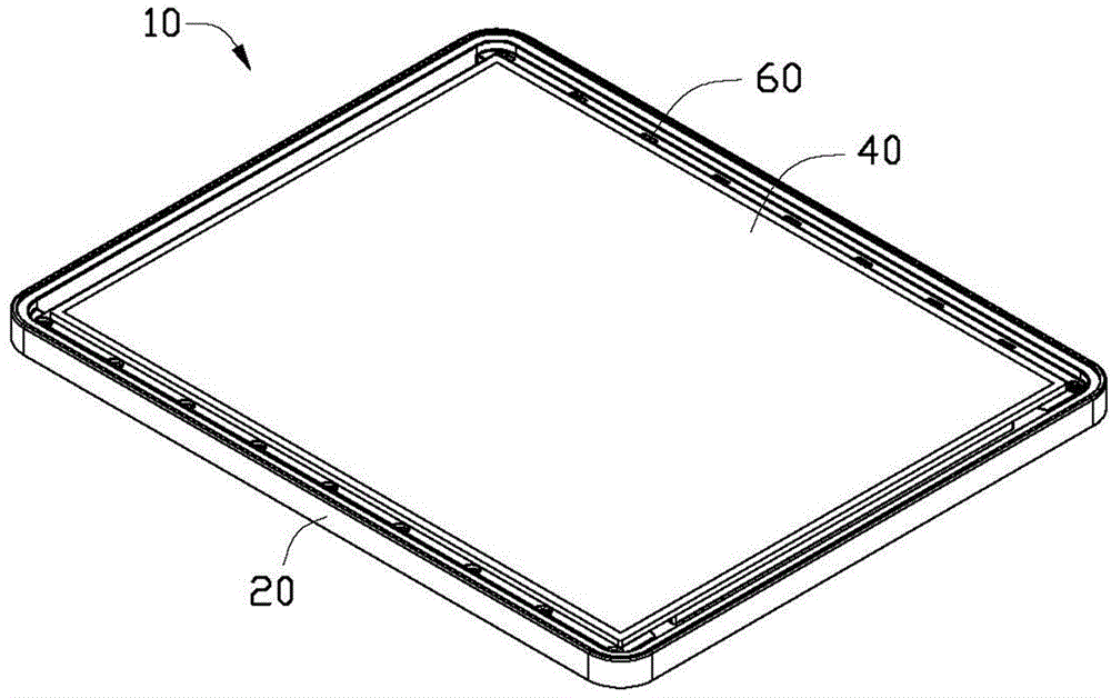
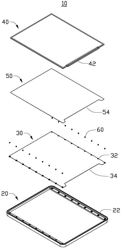
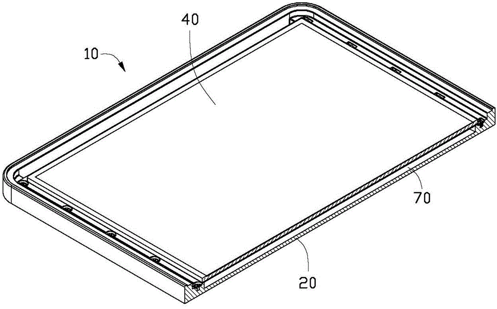
[0012] see Figure 1 to Figure 3 , the liquid crystal display device 10 includes a casing 20 , a fixing plate 30 , a liquid crystal panel 40 and an adhesive member 50 . The fixing plate 30 is fixed on the casing 20 . The adhesive member 50 is placed between the fixing plate 30 and the liquid crystal panel 40 for bonding the liquid crystal panel 40 to the fixing plate 30 . In the present invention, the liquid crystal display device 10 may be a monitor or a mobile electronic device with a liquid crystal display panel such as a tablet computer.

[0013] In this embodiment, a plurality of through holes 32 are symmetrically formed on the opposite two edges of the fixing plate 30, and a plurality of screw holes 22 corresponding to the plurality of through holes 32 are formed on the housing 20, and the fixing plate 30 passes through a plurality of The screws 60 respectively pass through the plurality of through holes 32 and are screwed to the plurality of screw holes 22 to be fixed...


PUM


Abstract

The invention provides a liquid crystal display device, which comprises a casing and a liquid crystal panel, and also comprises a fixing plate and a bonding element, wherein the fixing plate is fixedly arranged on the casing, and the bonding element is arranged between the fixing plate and the liquid crystal panel and is used for binding the liquid crystal panel onto the fixing plate.

Description

technical field [0001] The invention relates to a liquid crystal display device. Background technique [0002] In order to fix the liquid crystal panel in the existing liquid crystal display on the casing of the liquid crystal display, a plurality of screw holes are opened at the edge, and the liquid crystal display is fixed on the casing by screws. When the above-mentioned liquid crystal display is accidentally dropped, due to the shear force between the screw and the liquid crystal panel, the liquid crystal panel may break near the screw. Contents of the invention [0003] In view of this, the present invention provides a liquid crystal display device, which reduces the possibility of cracking when the liquid crystal panel is dropped. [0004] A liquid crystal display device, including a housing and a liquid crystal panel, the liquid crystal display device also includes a fixing plate and an adhesive member, the fixing plate is fixed on the housing, and the adhesive mem...

Claims


Application Information

Patent Timeline
Patent Type & Authority Applications(China)
IPC IPC(8): G02F1/1333
CPCG02F1/133308G02F2201/50G02F1/133325
Inventor 王川
Owner FU TAI HUA IND SHENZHEN
Why Eureka
Try Eureka