Gas pipeline system laying structure and laying method

A gas pipeline and pipeline technology, which is applied in pipeline laying and maintenance, mechanical equipment, pipes/pipe joints/pipe fittings, etc., can solve the problems of pipeline equipment and building damage, waste of resources, leakage of transported gas, etc., and reduce the risk of rupture Possibility, improved seismic capacity, and easy installation

Active Publication Date: 2019-09-17
深圳市中港建筑工程有限公司
View PDF8 Cites 8 Cited by
  • Summary
  • Abstract
  • Description
  • Claims
  • Application Information

AI Technical Summary

Problems solved by technology

[0003] Existing gas pipelines are buried inside the ground, but in the event of an earthquake, due to the large faults and landslides on the ground relative to the bathroom, this may cause the gas pipelines buried inside the ground to arch out of the ground, twisting, wrinkling and breaking , the pipeline equipment and buildings are also damaged, causing the gas to be transported to leak, which will cause serious waste of resources, and there may be a big explosion, which will affect people's life safety, so there is an urgent need for an earthquake-resistant gas pump with better earthquake resistance. Pipeline fixing methods to reduce the possibility of pipeline damage during earthquakes

Method used


Image

  • Gas pipeline system laying structure and laying method
  • Gas pipeline system laying structure and laying method
  • Gas pipeline system laying structure and laying method

Examples


Embodiment 1

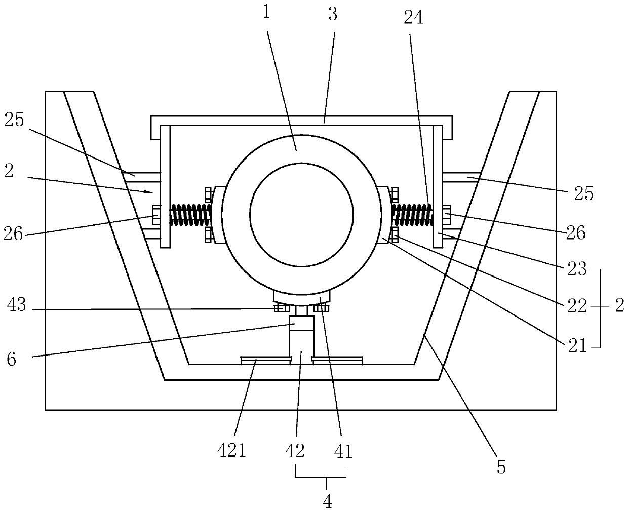
[0041] refer to figure 1 , the present invention provides a gas pipeline system laying structure, including a pipeline 1, an installation component 2, a cover plate 3 and a support component 4, when installing the pipeline 1, first set up a laying groove on the ground according to the extension direction of the pipeline 1 5. Then put the support assembly 4 on the bottom of the laying groove 5, then place the pipe 1 above the support assembly 4, install the assembly 2 on both sides of the pipe 1, and install the assembly 2 to the pipe 1 in the laying groove 5, the position inside is fixed, and finally the cover plate 3 is horizontally arranged above the pipeline 1, and finally sand is filled inside the laying groove 5. In this way, the laying of the pipeline 1 is completed.

[0042] refer to figure 1 , the mounting assembly 2 includes a mounting plate 21, a fixing bolt 22, a fixing plate 23 and a first elastic member, the mounting plate 21 is adapted to the outer surface of t...

Embodiment 2

[0057] A method for laying a gas pipeline 1 system, comprising the following steps:

[0058] S1, dig out the laying groove 5 on the ground along the laying direction of the pipeline 1;

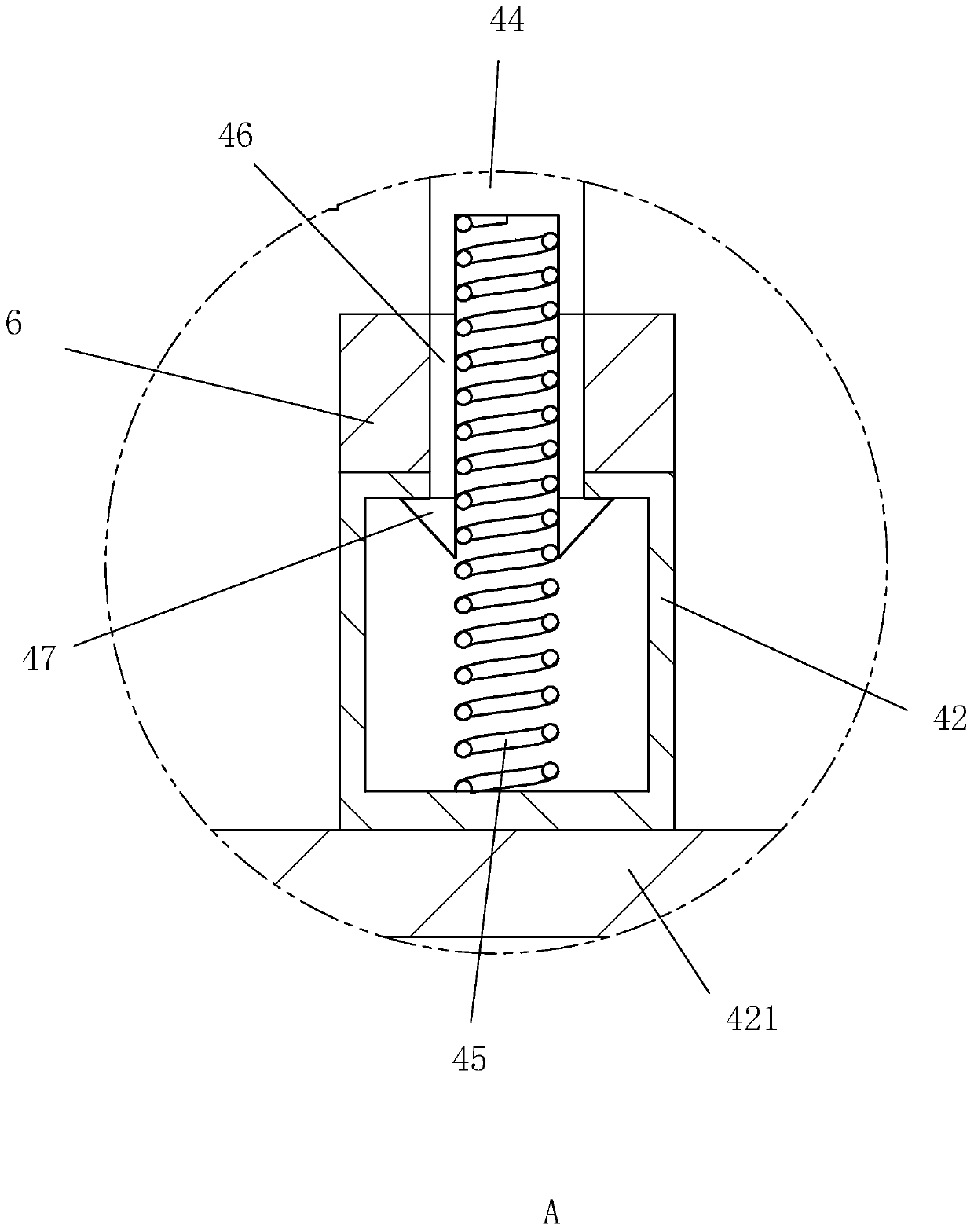
[0059] S2. Concrete is poured on the bottom wall and side wall of the laying groove 5, and the fixing plate 23 and the receiving rod 25 are prefabricated together with the side wall of the laying groove 5 using steel bars and concrete at the same time, and the bottom of the laying groove 5 is aligned with T type slide rail 421 for pouring;

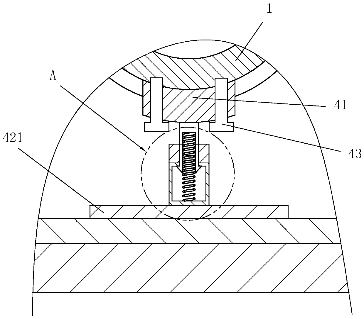
[0060] S3, use positioning bolts 43 to fix the support plate 41 on the peripheral surface of the pipeline 1, and place the pipeline 1 with the support plate 41 installed inside the laying groove 5;

[0061] S4, adding fine sand to the inside of the laying tank 5;

[0062] S5. Insert the auxiliary bolt 26 into the fixing plate 23 and rotate the auxiliary bolt 26, and use the fixing bolt 22 to fix the mounting plate 21 on the side wall of the pipeline 1; ...


PUM


Abstract

The invention relates to the field of gas pipeline laying, in particular to a gas pipeline system laying structure and a laying method. The system comprises a pipeline, wherein a laying groove is formed in the ground along the laying direction of the pipeline, the pipeline is laid in the laying groove, installation components are arranged on the two sides of the pipeline, the installation components comprise a mounting plate, a fixing bolt, a fixing plate and a first elastic part, the mounting plate is arranged on the peripheral surface of the pipeline and is embedded into the side wall of the pipeline, the fixing bolt is arranged on one side, far away from the pipeline, of the mounting plate and fixes the mounting plate on the pipeline, the fixing plate is vertically arranged on the two sides of the pipeline, the first elastic part is arranged between the fixing plate and the mounting plate, when the mounting plate is arranged on the side wall of the pipeline, the first elastic part is in a stretching state, and a supporting component used for supporting the pipeline is arranged at the bottom of the laying groove, so that the effects of improving the anti-seismic capacity of the pipeline and reducing the possibility of pipeline break are achieved.

Description

technical field [0001] The invention relates to the field of gas pipeline laying, in particular to a gas pipeline system laying structure and a laying method. Background technique [0002] At present, gas pipelines are used to transport natural gas, which is the way to transport large quantities of natural gas on land. Gas pipelines account for about half of the world's total pipeline length. [0003] Existing gas pipelines are buried inside the ground, but in the event of an earthquake, due to the large faults and landslides on the ground relative to the bathroom, this may cause the gas pipelines buried inside the ground to arch out of the ground, twisting, wrinkling and breaking , the pipeline equipment and buildings are also damaged, causing the gas to be transported to leak, which will cause serious waste of resources, and there may be a big explosion, which will affect people's life safety, so there is an urgent need for an earthquake-resistant gas pump with better ear...

Claims


Application Information

Patent Timeline
Patent Type & Authority Applications(China)
IPC IPC(8): F16L1/028F16L1/06
CPCF16L1/028F16L1/06
Inventor 刘新晶
Owner 深圳市中港建筑工程有限公司
Why Eureka
Try Eureka