
Array substrate, display panel and detection method for array substrate

A technology for an array substrate and a display panel, which is applied in the field of display and can solve the problems of micro-bright spots, inability to detect short circuits between shared capacitors and sub-pixel electrodes, and short circuits between shared capacitors and sub-pixel electrodes.

Active Publication Date: 2015-04-29
TCL CHINA STAR OPTOELECTRONICS TECH CO LTD
View PDF4 Cites 0 Cited by
  • Summary
  • Abstract
  • Description
  • Claims
  • Application Information

AI Technical Summary

Problems solved by technology

The uppermost layer of the shared capacitor is usually a transparent conductive layer, such as ITO, and ITO residues may appear in the actual production process, which will cause a short circuit between the shared capacitor and the sub-pixel electrode
When the shared capacitor is short-circuited with the sub-pixel electrodes, micro bright spots will appear on the display panel of the liquid crystal display device, resulting in poor display quality of the display panel.
Moreover, the short circuit between the shared capacitor and the sub-pixel electrode cannot be detected in the prior art

Method used


Image

  • Array substrate, display panel and detection method for array substrate
  • Array substrate, display panel and detection method for array substrate
  • Array substrate, display panel and detection method for array substrate

Examples


Embodiment Construction

[0021] The technical solutions in the embodiments of the present invention will be clearly and completely described below with reference to the accompanying drawings in the embodiments of the present invention. Obviously, the described embodiments are only a part of the embodiments of the present invention, but not all of the embodiments. Based on the embodiments of the present invention, all other embodiments obtained by those of ordinary skill in the art without creative efforts shall fall within the protection scope of the present invention.

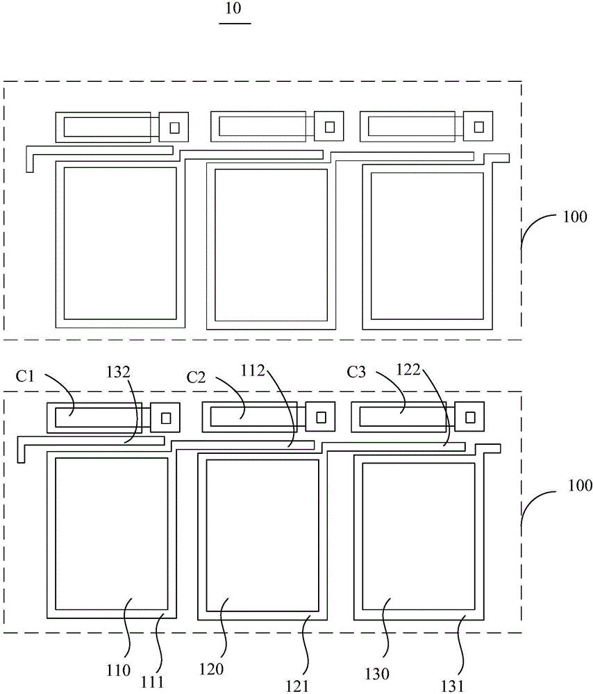
[0022] see figure 1 , figure 1 It is a schematic structural diagram of an array substrate according to a preferred embodiment of the present invention. The thin film transistor array 10 includes a plurality of pixels 100 distributed in a matrix, each pixel 100 includes a plurality of sub-pixels arranged in sequence, each sub-pixel is opposite to a capacitor and arranged at intervals, and each sub-pixel includes A sub-pixel electrode...


PUM


Abstract

The invention provides an array substrate, a display panel and a detection method for the array substrate. The array substrate includes a plurality of pixels distributed in a matrix, wherein each pixel includes a plurality of sub-pixels sequentially arranged, each sub-pixel is arranged to be opposite to and spaced apart from a capacitor, at least one sub-pixel includes an extending part, and the extending part of the sub-pixel electrode of the at least one sub-pixel is arranged to be corresponding to a gap between the adjacent sub-pixel and the capacitor corresponding to the adjacent sub-pixel.

Description

technical field [0001] The present invention relates to the field of display, in particular to an array substrate, a display panel and a detection method for the array substrate. Background technique [0002] As a common electronic device, liquid crystal display devices are widely used due to their advantages of light weight and large viewing angle. In order to change the color shift phenomenon that occurs in a vertically oriented performance display device at a large viewing angle, a pixel design with charge sharing is usually used. In a charge-sharing pixel design, each pixel includes three sub-pixels arranged in sequence, such as a red sub-pixel (R), a green sub-pixel (G), and a blue sub-pixel (B), and each sub-pixel includes a sub-pixel electrode , each pixel is opposed to a shared capacitor. The uppermost layer of the shared capacitor is usually a transparent conductive layer, such as ITO. In the actual production process, there may be residual ITO, which will cause a...

Claims


Application Information

Patent Timeline
Patent Type & Authority Applications(China)
IPC IPC(8): G02F1/1362G02F1/1343G02F1/13
CPCG02F1/1343G02F1/1362G02F1/136254G02F1/134309G09G3/006G09G2320/029G09G2330/12G01R31/52G02F1/134345G09G3/3607
Inventor 陈政鸿
Owner TCL CHINA STAR OPTOELECTRONICS TECH CO LTD
Learn More