
Low-voltage test circuit and method for initiating explosive device

A technology for testing circuits and testing methods, applied in the direction of measuring electricity, measuring electrical variables, measuring devices, etc., can solve the problems of inability to test small-scale changes of bridge wires, difficulty in testing single bridge wire faults, and cumbersome test circuits, and achieve judgment. The method is simple, the number of components is small, and the test circuit is simple

Active Publication Date: 2012-07-11
BEIJING AEROSPACE AUTOMATIC CONTROL RES INST +1
View PDF7 Cites 23 Cited by
  • Summary
  • Abstract
  • Description
  • Claims
  • Application Information

AI Technical Summary

Problems solved by technology

[0003] At present, the low-voltage test method of pyrotechnic products generally adopts the method of current source. This test method can test the open circuit fault of pyrotechnic products, but cannot test the small-scale change of the resistance of the bridge wire, especially in the case of double bridge wires used in parallel. It is more difficult to test the failure of single bridge wire
At the same time, there are many circuit parameters that need to be adjusted on site for each set of products, and the test circuit is relatively cumbersome.

Method used


Image

  • Low-voltage test circuit and method for initiating explosive device
  • Low-voltage test circuit and method for initiating explosive device
  • Low-voltage test circuit and method for initiating explosive device

Examples


Embodiment Construction

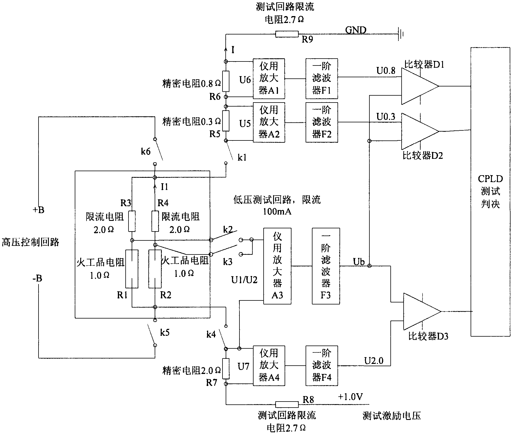
[0022] as attached figure 1 As shown, the pyrotechnics low-voltage test circuit is composed of double bridge wire pyrotechnics resistors R1, R2, pyrotechnics current-limiting resistors R3, R4, detection resistors R5, R6, R7 (accuracy is not less than ±0.1% A purely resistive circuit composed of the precision resistors), current limiting resistors R8, R9. Switches k5 and K6 are used to cut off the high-voltage control circuit of pyrotechnic products, and switches K1-K4 are used to connect to the low-voltage test circuit. The low-voltage differential signals generated on the double-bridge wire pyrotechnics resistors and detection resistors are respectively amplified and converted into single-ended output voltage signals through the instrument amplifier, and then the four single-ended output voltage signals are respectively filtered to generate pyrotechnics respectively. Product comparison voltage Ub and three reference comparison voltages U0.3, U0.8, U2.0, and the processing re...


PUM


Abstract

The invention discloses a low-voltage test circuit and a low-voltage test method for an initiating explosive device. The method comprises the following steps of: (1) disconnecting a high-voltage control loop of the initiating explosive device, and applying test excitation voltage to the low-voltage test circuit; (2) converting low-voltage differential signals on a resistor R1 and a resistor R2 of a double-bridge wire initiating explosive device into a single-ended output signal by using an instrument amplifier, amplifying, outputting to a filter, filtering the signal by using the filter, and outputting comparison voltage Ub; (3) amplifying low-voltage differential signals on a detection resistor R5, a detection resistor R6 and a detection resistor R7, converting and filtering to generate three reference comparison voltages, namely U0.3, U0.8 and U2.0; (4) comparing the Ub with the U0.3, the U0.8 and the U2.0 by using three comparators respectively; and (5) determining the current state of the initiating explosive device through a comparison result. The low-voltage test circuit is simple and reliable, a small number of elements are used, a test loop is not required to be charged with accurate current, the circuit does not have parameters required to be adjusted, and the judgment method is simple.

Description

technical field [0001] The invention relates to a design method and a circuit for performing low-voltage testing on a path of pyrotechnics by using a precision resistor, and belongs to the field of built-in testing (BIT) of bombing equipment of a weapon system. Background technique [0002] In the process of testing missiles and launch vehicles, the testing of pyrotechnics is a key test item. The pyrotechnics test is divided into two parts: low-voltage test and high-voltage test. In tactical weapons, only high-voltage tests are generally carried out, that is, the control loop test of pyrotechnics. In strategic weapons or launch vehicles, both high and low-voltage tests of pyrotechnics are required. conduct. The low-voltage test can test the on-off and resistance changes of the pyrotechnic product. The open circuit of the pyrotechnic product will cause the pyrotechnic product to fail to detonate normally; If the effective working current is not reached, it will also cause t...

Claims


Application Information

Patent Timeline
Patent Type & Authority Applications(China)
IPC IPC(8): G01R31/02
Inventor 魏守嵘
Owner BEIJING AEROSPACE AUTOMATIC CONTROL RES INST
Learn More