
Photoelectric display device and detection device and method

A photoelectric display and display medium technology, applied in the detection field, can solve problems such as weakening electric field strength and circuit substrate wear, and achieve the effects of reducing detection voltage, enhancing reliability and durability

Inactive Publication Date: 2016-11-23
SHANGHAI JIXIAN ELECTRONICS TECH
View PDF4 Cites 1 Cited by
  • Summary
  • Abstract
  • Description
  • Claims
  • Application Information

AI Technical Summary

Problems solved by technology

However, the thinner the substrate is, the easier it is to be worn by the circuit substrate when it frequently contacts the circuit substrate. Therefore, the display screen needs to keep a certain distance from the circuit substrate, but the existence of this distance will also weaken the electric field strength loaded on the liquid crystal.

Method used


Image

  • Photoelectric display device and detection device and method
  • Photoelectric display device and detection device and method
  • Photoelectric display device and detection device and method

Examples


Embodiment 1

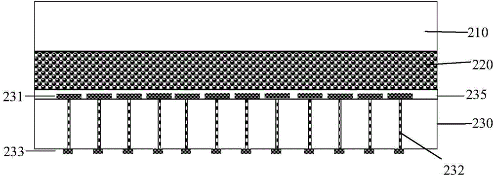
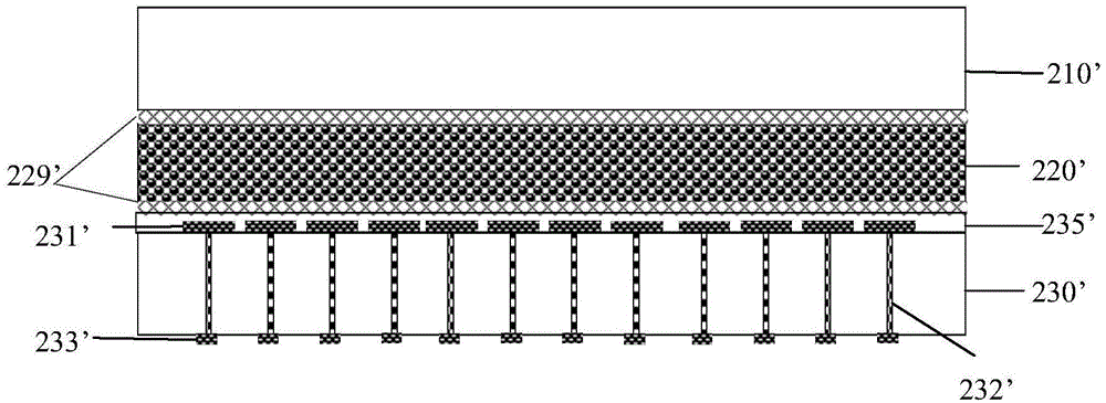
[0081] Image 6 It is a schematic cross-sectional view of an optoelectronic display device for detecting a circuit substrate with a conductive via open circuit according to the present invention; Figure 7A is the detection of the present invention Image 6 A schematic plan view of a matrix of conductive vias in the circuit substrate shown; Figure 7B is the detection of the present invention Image 6 The photoelectric display device of the shown circuit substrate shows a schematic plan view. Incorporate references Image 6 , Figure 7A , 7B , the main components of the optoelectronic display device in Example 1 and their corresponding connection relationships are similar to the above-mentioned implementations. The circuit characteristic detection device of the present invention detects such as Image 6 When there is a circuit substrate with a conductive via open circuit shown, the specific detection scheme is as follows:

[0082] a. Provide the optoelectronic display d...

Embodiment 2

[0087] Figure 8 It is a schematic cross-sectional view of an optoelectronic display device for detecting a circuit substrate with a short circuit between adjacent conductive vias according to the present invention; Figure 9A is the detection of the present invention Figure 8 A schematic plan view of a matrix of conductive vias in the circuit substrate shown; Figure 9B is the detection of the present invention Figure 8 The photoelectric display device of the shown circuit substrate shows a schematic plan view. Incorporate references Figure 8 , Figure 9A , 9B , the main components of the optoelectronic display device and the optoelectronic display device in Example 2 and their corresponding connection relationships are similar to the above-mentioned implementations. The circuit characteristic detection device of the present invention detects such as Figure 8 When there is a circuit substrate with a short circuit between adjacent conductive vias as shown, the specif...


PUM


Abstract

The invention provides a photoelectric display device and a detection device and method, and belongs to the technical field of circuit detection. The photoelectric display device comprises a substrate, an opposite substrate and a display medium. The substrate is provided with two side surfaces, one side surface is provided with multiple first electrode plates, the other side surface is correspondingly provided with multiple second electrode plates, each first electrode plate is electrically connected with the corresponding second electrode plate through a conductive hole, the opposite substrate and the substrate are oppositely arranged, and the display medium is arranged between the substrate and the opposite substrate. The detection method comprises the steps that voltage is applied to the photoelectric display device and a circuit substrate, and the photoelectric display device achieves the effect of an electric control light valve, so that circuit electric features are displayed on the photoelectric display device, finally, short circuit and disconnection conditions of a circuit can be accurately and visually judged, and the photoelectric display device and the detection device and method can be used for quality control over a surface-mounted circuit board.

Description

technical field [0001] The invention relates to the technical field of detection, in particular to an optoelectronic display device, a detection device and a method thereof for detection of surface mount circuit substrates. Background technique [0002] In recent years, liquid crystal display technology has developed rapidly. Liquid crystal display technology is an electro-optical conversion technology, that is, according to the magnitude of the electric field applied on both sides of the liquid crystal, the arrangement state of the liquid crystal is changed, thereby changing the direction of the light path through the liquid crystal layer, and finally changing the light output effect of the liquid crystal display device. [0003] like Figure 1A , 1B As shown, a detection device for detecting the electrical characteristics of a circuit substrate uses a PDLC type photoelectric display device 10 suspended on the circuit substrate 14 . in, Figure 1A Because the electro-opti...

Claims


Application Information

Patent Timeline
Patent Type & Authority Applications(China)
IPC IPC(8): G02F1/13G01R31/28
Inventor 李增强其他发明人请求不公开姓名
Owner SHANGHAI JIXIAN ELECTRONICS TECH
Learn More