Unmanned aerial vehicle remote sensing device and method

An unmanned aerial vehicle and remote sensing technology, applied in three-dimensional position/channel control, etc., can solve the problems of high flight conditions, low aerial photography accuracy, degradation, etc., and achieve the effect of improving imaging quality and aerial photography accuracy

Inactive Publication Date: 2015-04-29
河南四维远见信息技术有限公司
View PDF4 Cites 6 Cited by
  • Summary
  • Abstract
  • Description
  • Claims
  • Application Information

AI Technical Summary

Problems solved by technology

However, due to the influence of various disturbances on the existing unmanned aerial vehicle remote sensing devices equipped with aerial photography cameras, the movement of geographic information surveying and mapping aerial photography pan-tilts is actually a complex multi-mode high-order random motion, which makes the unmanned aerial vehicle remote sensing devices fly The attitude is changeable, and it is impossible to ensure that the aerial photography camera is always shooting vertically downward, which leads to the decline or even degradation of the imaging quality of remote sensing aerial photography images, which greatly affects the accuracy of remote sensing results, making aerial photography less accurate and narrow in application fields; further, due to remote sensing The technology is mainly for large-scale geographic information data collection. Existing aerial photogrammetry and remote sensing devices mostly use high-altitude aircraft and light and small aircraft as platforms. However, high-altitude aircraft and light and small aircraft have high requirements for flight conditions, and it is difficult to realize small low-altitude, high-precision, and quick-response geographic infor

Method used


Image

  • Unmanned aerial vehicle remote sensing device and method
  • Unmanned aerial vehicle remote sensing device and method
  • Unmanned aerial vehicle remote sensing device and method

Examples


Example Embodiment

[0025] Embodiments of the present invention will be described in detail below in conjunction with the accompanying drawings.

[0026] It should be clear that the described embodiments are only some of the embodiments of the present invention, not all of them. Based on the embodiments of the present invention, all other embodiments obtained by persons of ordinary skill in the art without creative efforts fall within the protection scope of the present invention.

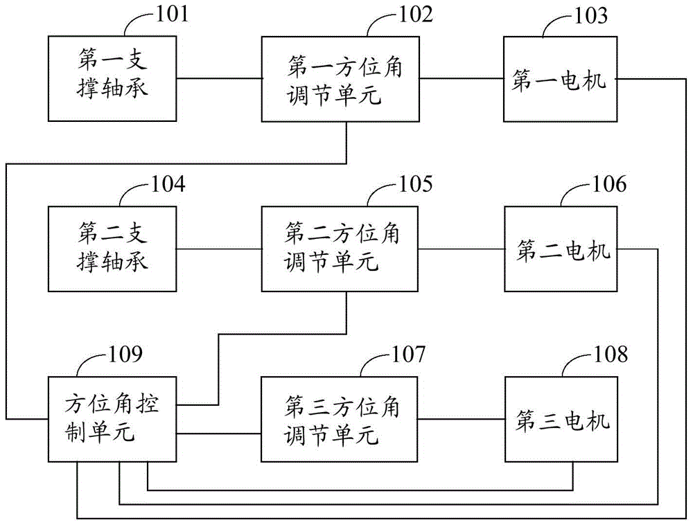
[0027] figure 1 It is a structural schematic diagram of the remote sensing device for the unmanned aerial vehicle of the embodiment of the present invention. see figure 1, the unmanned aircraft remote sensing device includes: a first support bearing 101, a second support bearing 104, a first motor 103, a second motor 106, a third motor 108, a first azimuth adjustment unit 102, a second azimuth adjustment unit 105. The third azimuth adjustment unit 107 and the azimuth control unit 109, wherein,

[0028] The azimuth...


PUM


Abstract

The embodiment of the invention discloses an unmanned aerial vehicle remote sensing device and method. The unmanned aerial vehicle remote sensing device comprises a first support bearing, a second support bearing, a first motor, a second motor, a third motor, a first azimuth regulation unit, a second azimuth regulation unit, a third azimuth regulation unit and an azimuth control unit, wherein the azimuth control unit is connected with the first azimuth regulation unit, the second azimuth regulation unit and the third azimuth regulation unit respectively; the first azimuth regulation unit is further connected with the first support bearing and the first motor respectively; the second azimuth regulation unit is connected with the second support bearing and the second motor respectively; the third azimuth regulation unit is connected with the third motor. Due to the application of the unmanned aerial vehicle remote sensing device disclosed by the invention, the accuracy and efficiency of aerial photography can be improved effectively.

Description

technical field [0001] The invention relates to aerial photogrammetry and remote sensing technology, in particular to an unmanned aerial vehicle remote sensing device and an unmanned aerial vehicle remote sensing method. Background technique [0002] With the continuous and rapid development of communication technology and aerial photography technology, various industries such as small area planning, industrial and mining area planning, new town construction, and strip construction projects increasingly need high-efficiency and high-precision geographic information through aerial photography. Surveying and mapping, for scientific planning and rational layout, makes the role of geographic information in macro decision-making and daily life increasingly significant. [0003] In aerial photography, because the UAV remote sensing device has the advantages of high cost performance, flexible take-off and landing, and wide application of environmental conditions, there are more and...

Claims


Application Information

Patent Timeline
IPC IPC(8): G05D1/10
Inventor 李军杰李世明杨保杨蒙蒙李志杰王丽媛张鹏飞焦禄宵张军利张小竞李天权
Owner 河南四维远见信息技术有限公司
Why Eureka
Try Eureka