
A device and method for realizing eye control intelligent terminal based on eye tracking

A technology for controlling smart terminals and eye tracking, applied in the input/output process of data processing, input/output of user/computer interaction, instruments, etc. Problems such as unsatisfactory control effect

Active Publication Date: 2017-09-05
成都九度九科技有限公司
View PDF5 Cites 0 Cited by
  • Summary
  • Abstract
  • Description
  • Claims
  • Application Information

AI Technical Summary

Problems solved by technology

[0004] Aiming at the problems in the above-mentioned prior art that the control effect on the smart terminal is not ideal, there are many electronic terminal function modules that can realize eye tracking control, the cost and popularity are high, and it is not conducive to its market promotion, the present invention provides an eye tracking based Device and method for realizing eyeball control intelligent terminal

Method used


Image

  • A device and method for realizing eye control intelligent terminal based on eye tracking
  • A device and method for realizing eye control intelligent terminal based on eye tracking
  • A device and method for realizing eye control intelligent terminal based on eye tracking

Examples


Embodiment 1

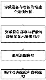
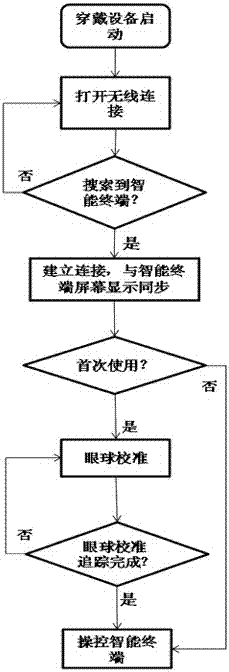
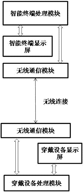
[0034] Such as Figure 1 to Figure 4 As shown, a device and method for controlling an intelligent terminal based on eyeball tracking, the method is used in a wearable device to realize wireless data transmission between the wearable device and the intelligent terminal, so as to control the intelligent terminal and obtain information on the intelligent terminal purpose, including the following steps:

[0035] A. Establish a wireless data connection with the smart terminal, read from the processor of the smart terminal to the screen display data output;

[0036] B. Display the above screen display data output on the wearable device in real time;

[0037] C. The user uses the image displayed on the wearable device as the measured object of the eye. The wearable device recognizes the user's eyeball movement or the area on the wearable device display screen that the user looks directly at, and wirelessly signals the eyeball movement or the area where it acts. transmitted to the s...

Embodiment 2

[0046] The present embodiment is further limited on the basis of embodiment 1, as Figure 1 to Figure 6 As shown, among them, Figure 5 It is a screen display, in which the arrow shown is the cursor, the three function key icons are paralleled below the picture, and the remaining 6 icons are calibration point icons; Figure 6 It is a screen display, in which the arrow shown is the cursor, and below the picture are three function key icons arranged side by side, and the dotted line indicates the cursor track.

[0047] When the eyeball movement is used on the screen of the wearable device, in order to improve the accuracy of eyeball movement tracking and recognition and facilitate the operation accuracy of the eyeball control smart terminal, the step C also includes an eyeball tracking calibration step for eyeball state capture calibration.

[0048] As an implementation scheme of a calibration step that is easy to implement and has an intuitive calibration effect, the eye track...


PUM


Abstract

The invention discloses a device and method for realizing eyeball control intelligent terminal based on eyeball tracking, which is used in a wearable device to realize wireless data transmission between the wearable device and the intelligent terminal, and achieve the goal of controlling the intelligent terminal and obtaining information on the intelligent terminal The purpose is to solve the problems in the prior art that the control effect of the smart terminal is not ideal, the electronic terminal function modules that can realize eye tracking control are many, the cost and popularization are high, and it is not conducive to its market promotion. The method and method provided by the present invention The equipment is easy to popularize and use, and the development and promotion are simpler, which is conducive to improving the convenience of the operation of the existing intelligent terminal and the standby battery life of the existing intelligent terminal.

Description

technical field [0001] The present invention relates to the field of intelligent terminal control and equipment, in particular to an equipment and method for realizing eyeball control intelligent terminal based on eyeball tracking. Background technique [0002] Today's smart terminals have a high penetration rate and have become an important tool for people to obtain information in daily life, such as mobile phones, tablet computers, notebooks, especially smart terminals, no matter in waiting halls, waiting stations, or even on buses and subways, smart terminals Users use smart terminals frequently. Smart terminals need to be read and used by hand-held touch. In the case that some users are not convenient to hold In a quiet environment, the above-mentioned control technology cannot achieve an ideal control effect, and the operation mode of the smart terminal set in the prior art is extremely inconvenient for the user in some cases. [0003] The invention patent with applica...

Claims


Application Information

Patent Timeline
Patent Type & Authority Patents(China)
IPC IPC(8): G06F3/01G06F3/0487
CPCG06F3/013G06F3/04812G06V40/50
Inventor 王露
Owner 成都九度九科技有限公司
Learn More