
Novel residual current circuit-breaker circuit

A residual current and circuit breaker technology, applied in the field of new residual current circuit breaker circuits, can solve the problems of inability to use high-power, large-value step-down resistors, inconvenient for distribution boxes to cooperate and assemble, and reduce circuit reliability. The effect of high anti-electromagnetic compatibility, improving anti-interference ability and improving reliability

Inactive Publication Date: 2015-04-29
CNC ELECTRIC GRP
View PDF10 Cites 0 Cited by
  • Summary
  • Abstract
  • Description
  • Claims
  • Application Information

AI Technical Summary

Problems solved by technology

Its disadvantages: the product volume is larger than the original small residual current circuit breaker, which is inconvenient to cooperate with the distribution box; not only the structural design is complicated, but also the production cost is high, which is not conducive to the actual demand of the market
At the same time, the power circuit adopts the form of full-wave rectification and resistance step-down, because the DC output voltage of the full-wave rectification circuit is about 0.9 times the AC input voltage; in order to meet the requirements of the working current of the residual current detection unit and the product structure volume, the resistance drop The voltage drop circuit cannot use a high-power, large-value drop resistor. The common method is to use two resistors in series to reduce the temperature rise, so that the temperature rise of the drop resistor is relatively high during normal operation, thereby reducing the reliability of the entire circuit. sex.

Method used


Image

  • Novel residual current circuit-breaker circuit
  • Novel residual current circuit-breaker circuit

Examples


Embodiment Construction

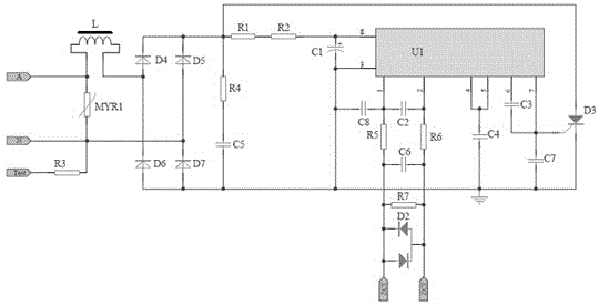
[0015] see figure 1 , is the circuit schematic diagram of the traditional residual current circuit breaker. Such as figure 1 As shown, the power circuit adopts the form of full-wave rectification and resistance step-down, because the DC output voltage of the full-wave rectification circuit is about 0.9 times the AC input voltage; in order to meet the requirements of the working current of the residual current detection unit and the product structure volume, Resistive step-down circuits cannot use high-power, high-value drop-down resistors. The common method is to use two resistors in series to reduce temperature rise; there is no overvoltage protection function. If you need to be equipped with an overvoltage protection function, the product must be configured A dedicated overvoltage protection module is used to achieve overvoltage protection, resulting in a product that is larger than the original small residual current circuit breaker, which is inconvenient to assemble with ...


PUM


Abstract

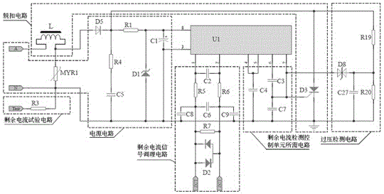
The invention relates to a novel residual current circuit-breaker circuit which comprises a power input. The novel residual current circuit-breaker circuit is characterized by further comprising a power circuit, a residual current signal conditioning circuit, a residual current detection and control unit, a circuit needed by the residual current detection and control unit, a residual current test circuit, an overvoltage detection circuit and a trip circuit, wherein the power circuit comprises a surge suppression circuit, a half-wave rectifying circuit, a resistance voltage reduction circuit , an external voltage stabilizing circuit and a filter circuit. The novel residual current circuit-breaker circuit is simple in design, and high in electromagnetic compatibility resistance characteristic, a residual current circuit-breaker is completely identical with small residual current circuit-breaker circuits in size, and the residual current circuit-breaker circuit solves the problem that a traditional small overvoltage protection type residual current circuit-breaker needs to be provided with an overvoltage module, as a result, the size of the traditional small overvoltage protection type residual current circuit-breaker is increased, and the traditional small overvoltage protection type residual current circuit-breaker can not be conveniently assembled on a distribution box in a matched mode. The novel residual current circuit-breaker circuit is simple in structure design, low in production cost, and quite suitable for meeting the actual market requirements.

Description

technical field [0001] The invention relates to the technical field of circuit breakers, more specifically, to a novel residual current circuit breaker circuit. Background technique [0002] The traditional residual current circuit breaker circuit has no overvoltage protection function. If it needs to be equipped with overvoltage protection function, the product must be equipped with a dedicated overvoltage protection module to realize overvoltage protection. Its disadvantages: the volume of the product is larger than that of the original small residual current circuit breaker, which is inconvenient to assemble with the distribution box; not only the structural design is complicated, but also the production cost is high, which is not conducive to the actual demand of the market. At the same time, the power circuit adopts the form of full-wave rectification and resistance step-down, because the DC output voltage of the full-wave rectification circuit is about 0.9 times of the...

Claims


Application Information

Patent Timeline
Patent Type & Authority Applications(China)
IPC IPC(8): H02H3/32
Inventor 余存泰肖义峰章火明李其利彭昆明
Owner CNC ELECTRIC GRP
Learn More