Robot charging method, device and system

A charging method and robot technology, which is applied in the field of robots, can solve the problems of being unable to manage the robot and knowing the power status of the robot in time, so as to achieve the effect of improving the positioning accuracy

Active Publication Date: 2015-04-29
深圳中智永浩机器人有限公司
View PDF6 Cites 29 Cited by
  • Summary
  • Abstract
  • Description
  • Claims
  • Application Information

AI Technical Summary

Problems solved by technology

[0005] Embodiments of the present invention provide a robot charging method, device, and system to solve the problem in the prior art that the robot cannot be informed of the power status of the robot in time when the robot is autonomously charged, and the robot that needs to be charged cannot be managed in an orderly manner.

Method used


Image

  • Robot charging method, device and system
  • Robot charging method, device and system
  • Robot charging method, device and system

Examples


Embodiment 1

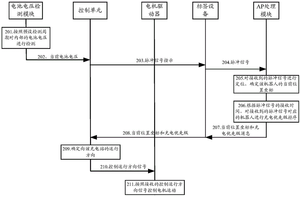
[0068] In Example 1 of the present invention, when the robot is autonomously charged, a tag device is installed on the robot (mobile body), and the tag device is used to send a pulse signal to the charging management device. The battery voltage detection module, control module, and motor driver inside the robot, And a label device, to realize the control of autonomous charging of the robot, wherein the charging management device is a wireless access point AP processing module. figure 2 It is a flow chart of a robot charging method provided in Embodiment 1 of the present invention, specifically including the following processing steps:

[0069] Step 201, the battery voltage detection module inside the robot detects the internal battery voltage according to a preset detection cycle.

[0070] Step 202, when the detected current battery voltage is lower than the threshold, the battery voltage detection module sends the current battery voltage to the control unit.

[0071] Among ...

Embodiment 2

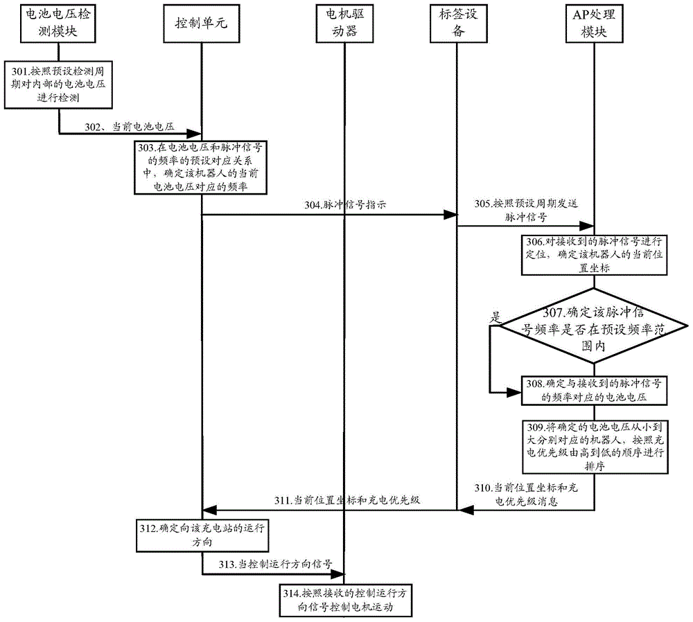
[0094] In Embodiment 2 of the present invention, when the robot is autonomously charged, a tag device is installed on the robot (mobile body), and the tag device is used to send a pulse signal to the charging management device. The battery voltage detection module, control module, and motor driver inside the robot, And a label device, to realize the control of autonomous charging of the robot, wherein the charging management device is a wireless access point AP processing module. image 3 It is a flow chart of a robot charging method provided in Embodiment 2 of the present invention, specifically including the following processing steps:

[0095] Step 301, the battery voltage detection module inside the robot detects the internal battery voltage according to a preset detection cycle.

[0096] Among them, the detected current battery voltage is the remaining power of the robot.

[0097] Step 302, the battery voltage detection module sends the detected current battery voltage t...

Embodiment 3

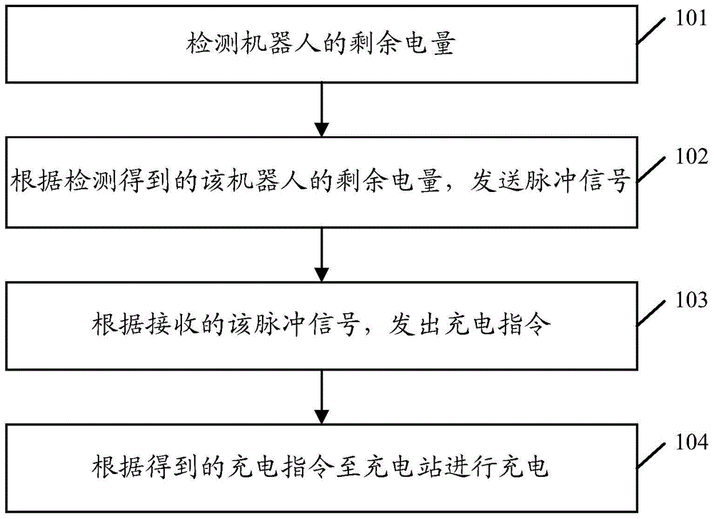
[0125] Based on the same inventive concept, according to the robot charging method provided by the above-mentioned embodiments of the present invention, correspondingly, Embodiment 3 of the present invention also provides a robot charging device, the structural diagram of which is as follows Figure 4 shown, including:

[0126] A detection unit 401, configured to detect the remaining power of the robot;

[0127] The request unit 402 is configured to send a pulse signal according to the detected remaining power of the robot;

[0128] A determining unit 403, configured to determine an operating instruction and a charging instruction according to the received pulse signal;

[0129] The charging unit 404 is configured to go to the charging station for charging according to the obtained charging instruction.

[0130] Further, the requesting unit 402 is specifically configured to send a pulse signal with a preset frequency when the remaining power of the robot is less than a thres...


PUM


Abstract

The invention discloses a robot charging method, device and system. The method includes the steps that the remaining electric quantity of a robot is detected; pulse signals are sent according to the detected remaining electric quantity of the robot; a charging instruction is sent out according to the received pulse signals; the robot goes to a charging station to be charged according to the obtained charging instruction. According to the scheme, the robot can find out the charging station to be charged in time, and the robot needing to be charged can be managed in an orderly mode; moreover, when positioning signals are used as the pulse signals to be sent, the robot can further be positioned through the pulse signals, and thus the positioning accuracy of the robot is improved.

Description

technical field [0001] The invention relates to the field of robots, in particular to a method, device and system for charging a robot. Background technique [0002] While robots assist or replace humans in completing various tasks, in order to ensure normal work, robots need to have sufficient energy. For a robot that uses electric energy, how to make the robot realize autonomous charging without human participation when the power is insufficient is the key to the normal operation of the robot. [0003] A common charging method for existing robots is to use infrared rays for autonomous charging, specifically: an infrared device is installed on the robot, and a sensor and a positioning server are installed on the charging device. When the robot confirms that it needs to be charged, it emits infrared rays through the infrared device signal; after the sensor on the charging device receives the infrared signal, it transmits the infrared signal data to the positioning server, a...

Claims


Application Information

Patent Timeline
Patent Type & Authority Applications(China)
IPC IPC(8): H02J7/00H01M10/44
CPCH01M10/441H02J7/0047H02J7/0048Y02E60/10
Inventor 徐泽贤丁宁于练熊丹张钦丽吴晖
Owner 深圳中智永浩机器人有限公司
Why Eureka
Try Eureka