
Assembly mold and assembly method of commutator

An assembly method and commutator technology, which are applied to electromechanical devices, manufacturing motor generators, electrical components, etc., can solve the problems of heavy weight of the transition plate and the middle sleeve plate, high use cost of the transition plate, and increased production cost, etc. The effect of structure optimization, high assembly efficiency and convenient disassembly and assembly

Inactive Publication Date: 2015-04-29
HUARUI ELECTRICAL APPLIANCE
View PDF7 Cites 0 Cited by
  • Summary
  • Abstract
  • Description
  • Claims
  • Application Information

AI Technical Summary

Problems solved by technology

[0004] In the traditional press process, the commutator is generally pressed through a single-cavity mold, three-cavity mold or four-cavity mold. The pressing operation process is as follows: knock the commutator segments into the sample ring one by one, and then press the sample ring into the to the transition plate, then press the commutator piece into the middle cover plate from the transition plate, and then start to press and keep warm. Although this traditional pressing process can basically meet the pressing of the commutator, there are still some technologies in the pressing process: Problems, 1. First pre-install the commutator plate, and then press the sample ring from the transition plate into the middle cover plate in turn. The whole assembly process is cumbersome, time-consuming and low in assembly efficiency; 2. The transition plate and the middle cover plate The weight of the sets of boards is very heavy, and the labor intensity of the staff in the assembly process is relatively high, and there are certain safety hazards; 3. There are many accessories related to the transition board, and the cost is high. cost of production

Method used


Image

  • Assembly mold and assembly method of commutator
  • Assembly mold and assembly method of commutator
  • Assembly mold and assembly method of commutator

Examples


Embodiment Construction

[0030] The following are specific embodiments of the present invention and in conjunction with the accompanying drawings, the technical solutions of the present invention are further described, but the present invention is not limited to these embodiments.

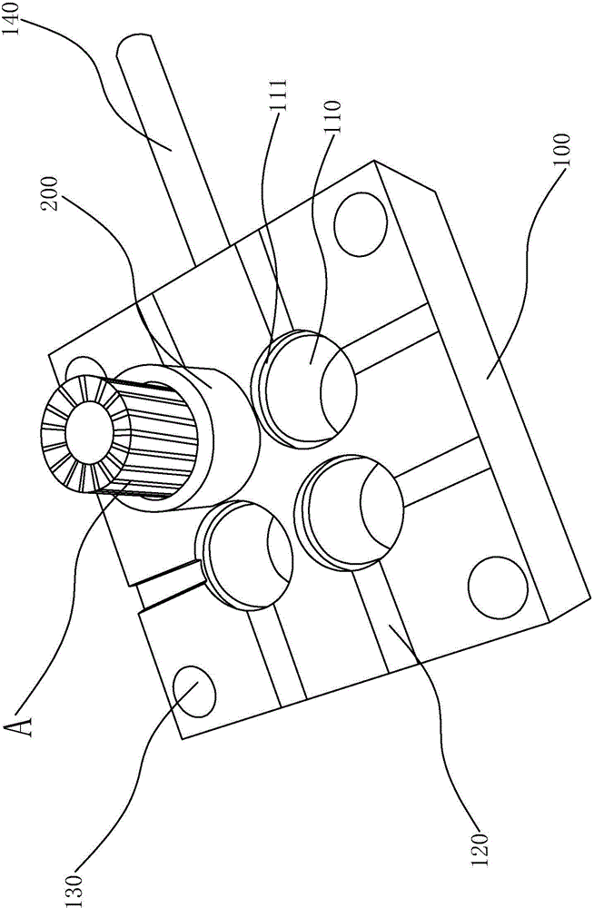
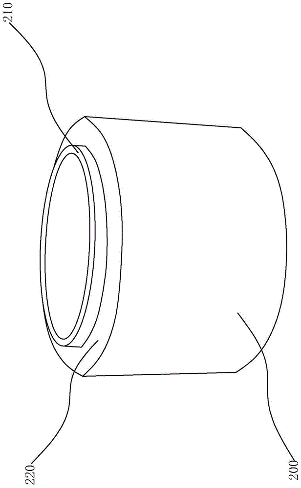
[0031] Such as figure 1 As shown, a commutator assembly mold includes a middle sleeve plate 100 and a positioning guide sleeve 200, the middle sleeve plate 100 is square, and the positioning guide sleeve 200 is circular tubular.

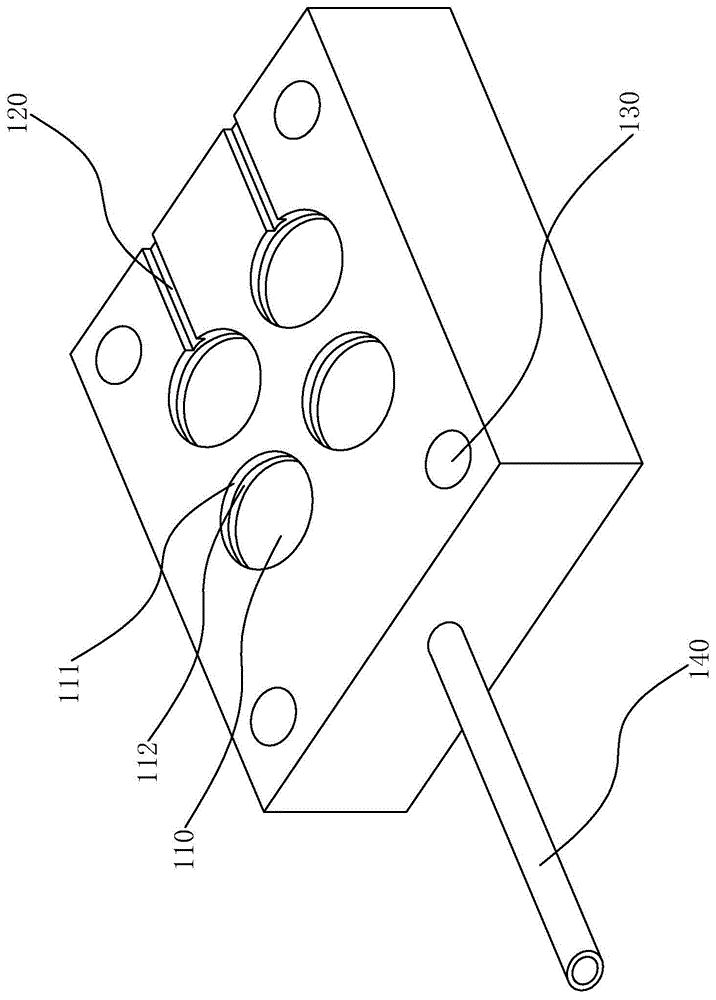
[0032] Such as figure 1 , figure 2 , Figure 4 , Figure 5 As shown, four assembly holes 110 that penetrate the middle casing 100 and are used to accommodate the commutator are opened on the middle casing 100, and the center line of the four assembly holes 110 forms a square. Of course, the assembly holes 110 The number is set according to actual needs, which can be more than four or less than four. Four coaxial countersunk holes 111 corresponding to the assembly holes 110 are provided on th...


PUM


Abstract

The invention provides an assembly mold and an assembly method of a commutator, and belongs to the technical field of commutator processing. The assembly mold solves the technical problems of complicated structure, low assembly efficiency and high cost of the existing assembly mold. The assembly mold of the commutator comprises a middle cleading, wherein a plurality of assembly holes penetrating through the middle cleading are formed in the middle cleading; a plurality of counterbore holes which correspond to and are coaxial with the assembly holes are formed in the end face of the middle cleading; first locating platforms are formed between the counterbore holes and the assembly holes; locating guide sleeves same as the inside diameters of the assembly holes are arranged on the middle cleading; an insertion and connection part and a second locating platform are formed at one end of each locating guide sleeve in a radial concaving manner; the insertion and connection parts are located in the counterbore holes, cling to inner side walls of the counterbore holes, and push against the first locating platforms; and the second locating platforms cling to the middle cleading. According to the assembly mold and the assembly method, accessories such as a transition plate are saved, and a flow of the commutator from the transition plate to the middle cleading is saved, so that a structure and a technology are simpler, the assembly efficiency of the commutator is higher, and the cost of the mold is lower.

Description

technical field [0001] The invention belongs to the technical field of commutator processing, and relates to an assembly mold, in particular to a mold for assembling a commutator. Background technique [0002] The commutator is the main part of the DC motor. Its main function is to commutate the current between the rotating winding and the stationary circuit components through the contact between the brush and the surface of the commutator, and convert the alternating potential of the armature winding It is converted into a DC potential between the brushes, or the external DC voltage is converted into an AC voltage and applied to the armature winding. [0003] The commutator is generally composed of a conductive part, an insulating part and a supporting fastening part. The conductive part is a commutating piece, and the commutating piece and the insulating part are arranged at intervals. , pressing and other times of baking and pressing to form a whole. [0004] In the tra...

Claims


Application Information

Patent Timeline
IPC IPC(8): H02K15/00
Inventor 陈岳祥孙瑞娣杨运动郁军波
Owner HUARUI ELECTRICAL APPLIANCE
Learn More