A Power Topology for Simultaneous Control of Three Switched Reluctance Motors

A technology for simultaneous control of switched reluctance motors, applied in multiple motor speed/torque control, etc., can solve the problem of increasing the development cost and hardware cost of power converters of switched reluctance motors, the inability to mass-produce, and the increase of switched reluctance Problems such as the complexity and cost of the motor power converter, to achieve the effect of shortening the product development cycle, improving the utilization rate of the winding, and making it easy to purchase

Active Publication Date: 2017-10-20
SOUTHEAST UNIV
View PDF7 Cites 0 Cited by
  • Summary
  • Abstract
  • Description
  • Claims
  • Application Information

AI Technical Summary

Problems solved by technology

[0004] However, an important technical bottleneck that limits the further popularization and application of the switched reluctance motor speed control system is the figure 1 As shown, the existing asymmetric bridge power converter topology of three-phase switched reluctance motor uses two main switches and two slow-flow diodes for each phase winding, which has six more power slow-flow diodes than ordinary asynchronous motor power converters.
Therefore, increasing the complexity and cost of the switched reluctance motor power converter
In addition, there is no uniform standard for switched reluctance motor power converters, which cannot be mass-produced, which greatly increases the development cost and hardware cost of switched reluctance motor power converters

Method used


Image

  • A Power Topology for Simultaneous Control of Three Switched Reluctance Motors
  • A Power Topology for Simultaneous Control of Three Switched Reluctance Motors
  • A Power Topology for Simultaneous Control of Three Switched Reluctance Motors

Examples


Embodiment Construction

[0023] The present invention will be further explained below in conjunction with the accompanying drawings.

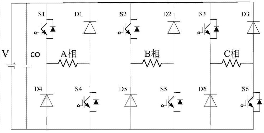
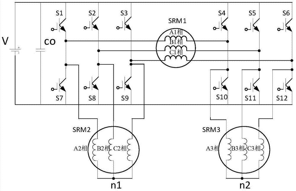
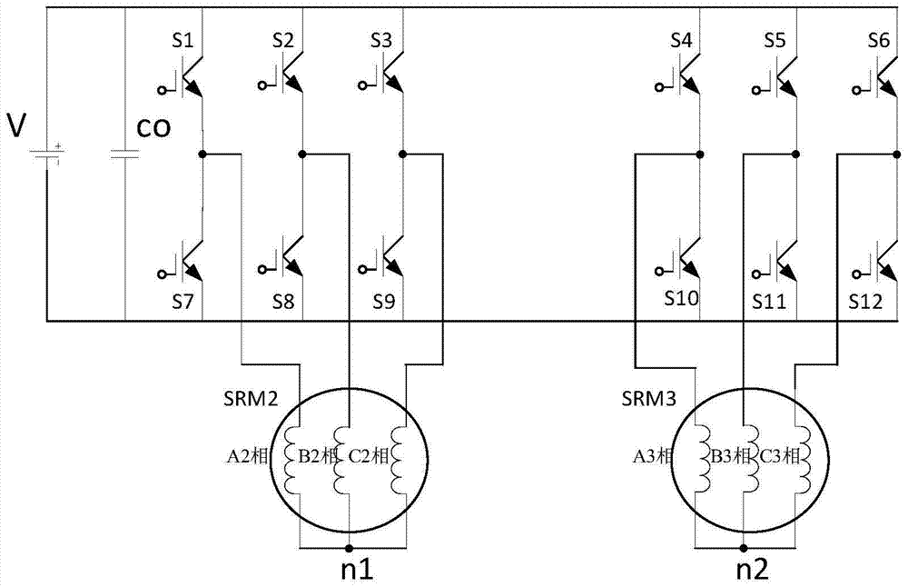
[0024] Such as figure 2 As shown, the present invention provides a power topology for simultaneously controlling three switched reluctance motors, mainly two three-phase bridge converters controlling the power topology for three three-phase switched reluctance motors, including DC power supply V, power supply Filter capacitor CO, 12 power switch tubes S1-S12, three three-phase switched reluctance motors No. 1 motor SRM1, No. 2 motor SRM2, and No. 3 motor SRM3.

[0025] No. 1 motor SRM1 includes A1 phase winding, B1 phase winding, C1 phase winding; No. 2 motor SRM2 includes A2 phase winding, B2 phase winding, C2 phase winding, No. 3 motor SRM3 includes A3 phase winding, B3 phase winding, C3 phase winding ; Neutral point n1, n2.

[0026] The power supply filter capacitor CO is connected in parallel to the two poles of the DC power supply V, and the positive pole of th...


PUM


Abstract

The invention discloses a power topological structure controlling three switch reluctance motors at the same time. The power topological structure comprises a direct-current power source, the three three-phase switch reluctance motors, a power filter capacitor and 12 power switch tubes. The power filter capacitor is connected with the two electrodes of the direct-current power source in parallel. The positive electrode of the direct-current power source is connected with the collector electrodes of the first power switch tube, the second power switch tube, the third power switch tube, the fourth power switch tube, the fifth power switch tube and the sixth power switch tube at the same time. The negative electrode of the direct-current power source is connected with the emitting electrodes of the seventh power switch tube, the eighth power switch tube, the ninth power switch tube, the tenth power switch tube, the eleventh power switch tube and the twelfth power switch tube at the same time. Through connection of windings of the motors, the three switch reluctance motors are controlled through switching-on and switching-off of a switch, and the idle motor or the faulty motor can be switched off. The problems that an existing switch reluctance motor drive power structure is complicated and high in cost, on some occasions, one or more motors are idler, the utilization rate of a power converter is low, and the work efficiency of a system is low are solved.

Description

technical field [0001] The invention relates to the field of motor manufacture and control, in particular to a power topology structure for simultaneously controlling three switched reluctance motors. Background technique [0002] With the development of power electronic device technology, microelectronic technology and automatic control technology, especially the price increase caused by the export restrictions of rare earth permanent magnet materials, the application of switched reluctance motors will become more and more extensive. On the other hand, in some special operating environments such as deep space, deep sea, and large temperature difference between day and night, the magnetic properties of permanent magnets are unstable, which is not conducive to the application of permanent magnet motors in the above fields. [0003] The switched reluctance motor is an electric excitation motor, its stator and rotor are laminated with ordinary silicon steel sheets to form a dou...

Claims


Application Information

Patent Timeline
Patent Type & Authority Patents(China)
IPC IPC(8): H02P6/04
CPCH02P6/04
Inventor 花为陆增洁赵桂书程明王宝安
Owner SOUTHEAST UNIV
Why Eureka
Try Eureka