
Emergency intelligent switching system of host/backup mode network physical link

A physical link and intelligent switching technology, applied in transmission systems, digital transmission systems, data exchange networks, etc., can solve the problems of high price, large investment, delayed fault recovery time, etc., achieve real-time transmission, realize large-flow data, The effect of improving data availability

Active Publication Date: 2015-04-29
重庆广用通信技术有限责任公司
View PDF4 Cites 1 Cited by
  • Summary
  • Abstract
  • Description
  • Claims
  • Application Information

AI Technical Summary

Problems solved by technology

This often requires network administrators to rush to the site immediately for manual operation, which delays the recovery time of the fault, and requires personnel with professional skills to complete the on-site operation. If you use equipment with active and standby functions, only high-end products have The price of equipment with this function is extremely high. For some small and medium-sized customers, it is out of reach, and products from different manufacturers are not compatible. Traditional routing equipment must use equipment from the same manufacturer, and a one-time investment is required to purchase the main equipment. And backup equipment, the initial investment is very large; the existing Bypass can only provide emergency protection for layer 2 network equipment, but it is powerless for layer 3 network equipment, only high-end products have the main and backup functions

Method used


Image

  • Emergency intelligent switching system of host/backup mode network physical link
  • Emergency intelligent switching system of host/backup mode network physical link
  • Emergency intelligent switching system of host/backup mode network physical link

Examples


Embodiment Construction

[0051] Hereinafter, preferred embodiments of the present invention will be described in detail with reference to the accompanying drawings. It should be understood that the preferred embodiments are only for illustrating the present invention, but not for limiting the protection scope of the present invention.

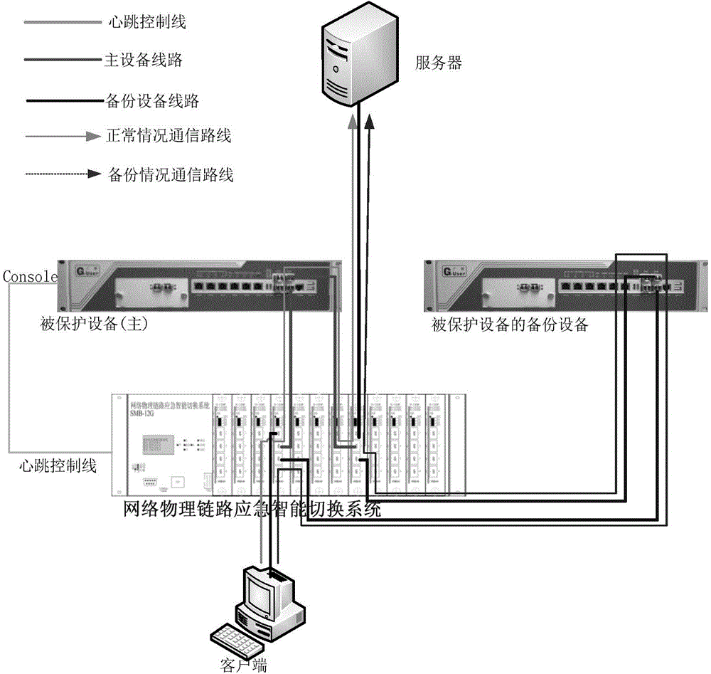
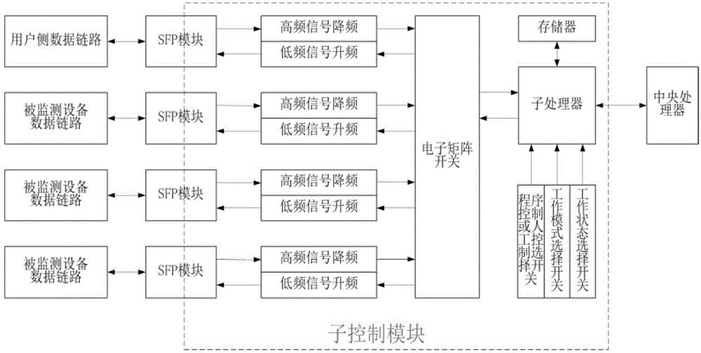
[0052] like Figure 1-4 As shown, an emergency intelligent switching system of a network physical link in master / backup mode provided by the present invention includes a server, a protected device, a backup device, a client, and a switching system;

[0053] The server is used to process and store network switching information;

[0054] The switching system is used to control the network physical link switching process;

[0055] The switching system includes a first sub-control module and a second sub-control module;

[0056] The server is connected to the input end of the first sub-control module; the output end of the first sub-control module is respectively connec...


PUM


Abstract

The invention discloses an emergency intelligent switching system of a host / backup mode network physical link. The emergency intelligent switching system comprises a server, protected equipment, standby equipment, a client, a first sub control module and a second sub control module, wherein the server is connected with the input end of the first sub control module; the output end of the first sub control module is respectively connected with input ends of the protected equipment and the standby equipment; output ends of the protected equipment and the standby equipment are connected with the input end of the second sub control module; the output end of the second sub control module is connected with the client; the protected equipment is connected with a switch system through a heartbeat control line. The switching system provided by the invention is suitable for switching the protected equipment to the standby equipment to ensure that a network is not influenced when the protected equipment fails. The switching system can be used for providing host / standby protection to different routing equipment. The switching system provides a flexible network equipment emergency protection scheme for a customer to help a network platform realize smooth and real-time transmission of a massive dataflow, thereby improving data availability, safety, stability and reliability.

Description

technical field [0001] The invention relates to the field of network security and switching, in particular to an emergency intelligent switching system for network physical links in master / standby mode. Background technique [0002] With the increasing demand for network broadband in all walks of life, 1000M networks and 1000M communications are gradually expanding in the network market, and firewalls, routers, and server products provided by major companies are also gradually replaced with 1000M links. Therefore, with the expansion of network bandwidth and the increase of the number of users, people pay more and more attention to network security and network stability. [0003] Network security devices are generally used between two or more networks, such as between an internal network and an external network. The application program in the network security device will analyze the network packets passing through it to determine whether there is a threat After processing, t...

Claims


Application Information

Patent Timeline
Patent Type & Authority Applications(China)
IPC IPC(8): H04L29/06H04L12/24
Inventor 赵跃邓敏王领黄胜范帅赵良斌於惠袁帅李陆平
Owner 重庆广用通信技术有限责任公司
Learn More