Accumulator

A technology of accumulator and bellows, applied in the direction of accumulator device, actuator accumulator, fluid pressure actuating device, etc., to reduce the number of parts, reduce the number of parts, and ensure the effect of sealing

Active Publication Date: 2015-04-29
EAGLE INDS
View PDF8 Cites 18 Cited by
  • Summary
  • Abstract
  • Description
  • Claims
  • Application Information

AI Technical Summary

Problems solved by technology

[0014] However, the Figure 13 The accumulators to date have room for improvement in the following areas

Method used


Image

  • Accumulator
  • Accumulator
  • Accumulator

Examples


Embodiment

[0094] Next, embodiments of the present invention will be described based on the drawings.

no. 1 example ·

[0095] First embodiment...

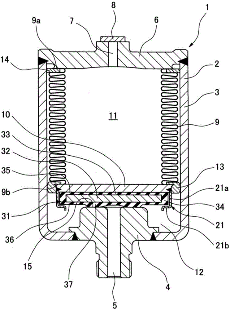
[0096] Figure 1 to Figure 5 The accumulator 1 according to the first embodiment of the present invention is shown. The accumulator 1 of this embodiment is a metal bellows type accumulator using a metal bellows as the bellows 9, and is configured as follows.

[0097] That is, if figure 1As shown, an accumulator case 2 having a port hole 5 connected to a pressure piping of an unillustrated device is provided, and a bellows 9 and a bellows cover 10 are arranged inside the case 2, and the parts of the case 2 are The inner space is partitioned into a gas chamber 11 in which a high-pressure gas (for example, nitrogen gas) is sealed, and a liquid chamber 12 in communication with the port hole 5 . As the housing 2, the bottomed cylindrical housing 3 is fixed (welded) to the bottom center of the housing 3 and the oil port 4 provided with the port hole 5 is fixed (welded) to the upper end of the housing 3. The housing is composed of the combination of ...

no. 3 example ·

[0122] (2) The third embodiment...

[0123] As a third embodiment, such as Figure 9 ~ Figure 11As shown, grooves 39 formed by partially reducing the thickness of the flexible portion 34 in the radial direction are provided on the port-side end surface and the non-port-side end surface of the flexible portion 34 of the sealing member 31 . According to this structure, similarly to the above-mentioned second embodiment, the amount of shear deformation of the flexible portion 34 can be increased, and the distance between the seal member 31 and the seal bracket 21 and between the seal member 31 and the bellows cover 10 can be increased. relative movement. In addition, in the figure, the outer peripheral protrusion 38 according to the above-mentioned second embodiment is provided together on the port side end face of the flexible portion 34, therefore, the groove portion 39 is provided on the inner peripheral side of the outer peripheral protrusion 38 on the port side end face. ....


PUM


Abstract

Provided is an accumulator, which: is capable of reducing the pressure difference that is generated by differences in coefficients of thermal expansion when liquid trapped in the liquid chamber and a sealed gas undergo thermal expansion during zero-down, thereby limiting the occurrence of plastic deformation in the bellows; and has a structure in which the parts are small and few in number. To achieve said purpose, the accumulator has a sealing member held on the port hole-side of the bellows cap via a seal holder. When operation of the machine is stopped and the pressure inside the pressure piping decreases, the sealing member contacts the sealing section and closes the liquid chamber. If liquid trapped in the liquid chamber when the liquid chamber is closed undergoes thermal expansion, the bellows cap moves in the direction away from the sealing section while the sealing member is still in contact with the sealing section. Since the sealing member is a rigid plate, the outer circumferential surface of which is covered by a flexible section obtained from a rubber-like elastic body, the flexible section allows relative movement of the bellows cap by undergoing shear deformation as a result of engagement with the seal holder.

Description

technical field [0001] The present invention relates to an accumulator used as a pressure storage device or a pulse pressure attenuation device. The accumulator of the present invention is used, for example, in hydraulic piping in vehicles such as automobiles. Background technique [0002] Currently, if Figure 12 As shown, there is known an accumulator in which a bellows 9 and a bellows cover 10 are arranged inside an accumulator case 2 having a port hole 5 connected to a pressure piping of the equipment, and the inside of the case 2 is The space is divided into a gas chamber 11 that seals high-pressure gas and a liquid chamber 12 that communicates with the port hole 5. In this accumulator, when the operation of the equipment stops and the pressure in the pressure piping decreases, the liquid (oil) in the liquid chamber 12 ) is gradually discharged from the port hole 5, and the bellows 9 gradually expands due to the enclosed air pressure, and the bellows cover 10 is in con...

Claims


Application Information

Patent Timeline
Patent Type & Authority Applications(China)
IPC IPC(8): F15B1/08
CPCF15B1/103F15B20/007F15B2201/3153F15B2201/3157F15B2211/865
Inventor 兵头大介三宅邦明山下松喜
Owner EAGLE INDS
Why Eureka
Try Eureka