
Fire disaster rescuing system

A fire and lifesaving platform technology, applied in the field of rescue systems, can solve problems such as slow evacuation speed, lack, and unsuitable number of rescuers, and achieve the effect of speeding up evacuation speed and improving rescue efficiency

Inactive Publication Date: 2015-05-06
CHONGQING JIAOTONG UNIVERSITY
View PDF9 Cites 3 Cited by
  • Summary
  • Abstract
  • Description
  • Claims
  • Application Information

AI Technical Summary

Problems solved by technology

[0002] In recent years, the threat and damage caused by fire to my country's booming economic construction have become increasingly serious, especially the fire losses of high-rise buildings and facilities are on the rise; high-rise building fires are also recognized as one of the most difficult types of fires in the world to rescue. There is no effective solution, and firefighters mainly use equipment such as vehicle-mounted ladders, vehicle-mounted aerial ladders, lifting platforms, and ground inflatable air cushions for rescue; however, these rescue equipment have some shortcomings. When rescuing people trapped in high-rise building fires Due to lack of high-altitude evacuation experience and nervousness, the rescued people often need to be accompanied by firefighters to evacuate safely, resulting in slow evacuation speed, prolonging the precious time of emergency evacuation, and resulting in low rescue efficiency; moreover, Existing rescue equipment also has the problem of insufficient rescue space, which is not suitable for occasions with a large number of rescuers

Method used


Image

  • Fire disaster rescuing system
  • Fire disaster rescuing system
  • Fire disaster rescuing system

Examples


Embodiment Construction

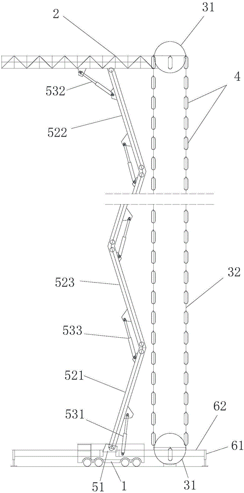
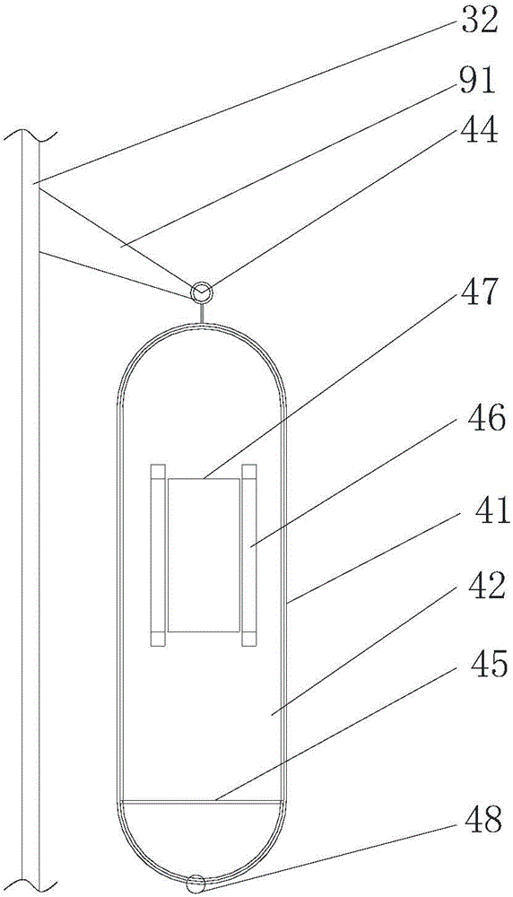
[0020] figure 1 It is a structural schematic diagram of the present invention, as shown in the figure: the fire rescue system of this embodiment includes a support body 1 provided with a lifting device and a lifesaving platform 2 arranged at the upper end of the lifting device. People's lifesaving device 4, described circulation device comprises the circulation control part 31 that is respectively arranged on lifesaving platform 2 and ground and is connected on two circulation control parts 31 and the ropeway 32 that circulates between two circulation control parts 31, described lifesaving The device 4 is connected to the cableway 32 and circulates synchronously with the cableway 32; the support body 1 is used to support the lifting device, and can maintain the balance of the lifting device; considering the convenience of control and transportation of the system, the support body 1 can be a motor vehicle, especially It is a trailer structure with better bearing capacity; the l...


PUM


Abstract

The invention discloses a fire disaster rescuing system. The fire disaster rescuing system comprises a supporting body provided with a hoisting device, and a life-saving platform arranged at the upper end of the hoisting device; the system further comprises a circulating device and life-saving devices for carrying people, wherein the circulating device comprises circulating control parts which are respectively arranged on the life-saving platform and on the ground, and a cableway which is connected with the two circulating control parts and is circulated between the two circulating control parts; the life-saving devices are connected with the cableway and are synchronously circulated along the cableway. According to the fire disaster rescuing system, when people trapped in a high-rise building by a fire disaster are being rescued, the life-saving devices are lifted to the height of the concentrated trapped people by the hoisting device, and firefighters command the trapped people to enter the life-saving devices from the life-saving platform and the trapped people are rapidly conveyed to the ground through the transportation of the cableway, so that the evacuation speed can be increased and the rescuing efficiency is improved; meanwhile, the plurality of life-saving devices are circularly moved between the life-saving platform and the ground under the action of the circulating device and enough rescuing space can be provided, so that the fire disaster rescuing system is suitable for being used in occasions with more people.

Description

technical field [0001] The invention relates to a rescue system, in particular to a fire rescue system. Background technique [0002] In recent years, the threat and damage caused by fire to my country's booming economic construction have become increasingly serious, especially the fire losses of high-rise buildings and facilities are on the rise; high-rise building fires are also recognized as one of the most difficult types of fires in the world to rescue. There is no effective solution, and firefighters mainly use equipment such as vehicle-mounted ladders, vehicle-mounted aerial ladders, lifting platforms, and ground inflatable air cushions for rescue; however, these rescue equipment have some shortcomings. When rescuing people trapped in high-rise building fires Due to lack of high-altitude evacuation experience and nervousness, the rescued people often need to be accompanied by firefighters to evacuate safely, resulting in slow evacuation speed, prolonging the precious ti...

Claims


Application Information

Patent Timeline
IPC IPC(8): A62B1/00
CPCA62B1/00
Inventor 林立
Owner CHONGQING JIAOTONG UNIVERSITY
Learn More