
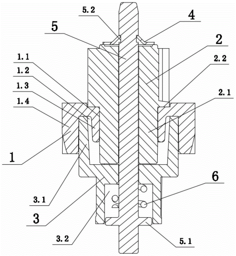
A skid mechanism for mirror driver of automobile rearview mirror

A technology for automobile rearview mirror and skid mechanism, which is applied to vehicle parts, optical observation devices, transportation and packaging, etc., can solve the problems of increasing the difficulty of manufacturing parts, complex structure of the skid mechanism, and increased failure rate of parts, and achieves assembly. The effect of convenience, simple structure and low cost of parts

Active Publication Date: 2017-01-11
NINGBO JINGCHENG CAR IND
View PDF4 Cites 1 Cited by
  • Summary
  • Abstract
  • Description
  • Claims
  • Application Information

AI Technical Summary

Problems solved by technology

[0005] However, the structure of the skid mechanism in the prior art is often more complex, so the cost is higher, the assembly is difficult, and the failure rate is further increased due to too many parts.
In addition, the sliding mechanism needs to be installed in the rearview mirror housing with limited volume, so too many components lead to smaller volumes of each component, which further increases the difficulty of manufacturing the components and increases the cost

Method used


Image

  • A skid mechanism for mirror driver of automobile rearview mirror
  • A skid mechanism for mirror driver of automobile rearview mirror

Examples


Embodiment Construction

[0018] The present invention will be further described below in conjunction with the accompanying drawings and specific embodiments.

[0019] The tight fit between the surfaces described below means that the surfaces are pressed tightly, and there is a certain friction coefficient value between the surfaces, so that a certain friction force is generated between the surfaces. When one surface is used as the active surface, the other surface is driven by the friction force as the passive surface, and when the resistance received by the passive surface continues to increase, a slip is formed between the surfaces, that is, the resistance overcomes Maximum static friction, which converts the force between the driving and driven surfaces into sliding friction.

[0020] Specifically, the above-mentioned tight fit includes between planes and planes, and also includes between the arc-shaped outer wall of the cylinder and the inner wall of the hole.

[0021] As shown in the figure, the...


PUM


Abstract

The invention discloses a slipping mechanism for a mirror surface driver of an automotive rearview mirror. The slipping mechanism comprises a rotation shaft (5), a straight-tooth wheel column (2) and an oblique-tooth disc (1) which sequentially sleeves the rotation shaft (5), as well as a limiting mechanism arranged on the rotation shaft (5) and used for limiting axial movement between the straight-tooth wheel column (2) and the oblique-tooth disc (1). The slipping mechanism is characterized in that a driving friction surface is arranged on the oblique-tooth disc (1); a driven friction surface matched with the driving friction surface is arranged on the straight-tooth wheel column (2); a friction force used for driving linkage of the straight-tooth wheel column (2) and the oblique-tooth disc (1) is formed between the driving friction surface and the driven friction surface; the maximum value of the friction force is smaller than the resistance generated by rotating the straight-tooth wheel column (2) to an extreme position. The slipping mechanism for the mirror surface driver of the automotive rearview mirror is simple in structure and can be used for effectively preventing the mirror surface from being broken by rotating out of travel when the mirror surface rotates to the extreme position.

Description

technical field [0001] The invention relates to the technical field of auto parts, in particular to a slipping mechanism of an auto rearview mirror mirror driver. Background technique [0002] As we all know, the car rearview mirror is an important accessory for safe driving of the car. It provides a good side and rear view for the driving process of the car, and is an important guarantee for the driving safety of the driver. However, the existing car driver's seat often needs to be adjusted according to the height and body shape of different drivers. Therefore, the rearview mirror of the car is required to be adjusted in angle, so as to meet the best side and rear views of different drivers. [0003] The above-mentioned adjustable angle of the automobile rearview mirror is usually provided in the mirror housing of the automobile rearview mirror with a rotating shaft used to drive the mirror to rotate, and the rotating shaft is driven by a driver and a transmission mechanism...

Claims


Application Information

Patent Timeline
Patent Type & Authority Patents(China)
IPC IPC(8): B60R1/062
CPCB60R1/062
Inventor 朱杨文
Owner NINGBO JINGCHENG CAR IND
Learn More