High-speed railway scheduling method and system realizing station dwell time change accurate to second

A technology of stopping time and stopping time, applied in the direction of automatic system, railway signal and safety, etc., can solve the problem of inability to accurately realize the arrival of high-speed trains in seconds.

Active Publication Date: 2015-05-06
BEIJING E HUALU INFORMATION TECH +1
View PDF5 Cites 5 Cited by
  • Summary
  • Abstract
  • Description
  • Claims
  • Application Information

AI Technical Summary

Problems solved by technology

[0010] When the above situation occurs due to the change of the stop time, the driver can only drive according to his o

Method used


Image

  • High-speed railway scheduling method and system realizing station dwell time change accurate to second
  • High-speed railway scheduling method and system realizing station dwell time change accurate to second
  • High-speed railway scheduling method and system realizing station dwell time change accurate to second

Examples


Embodiment 1

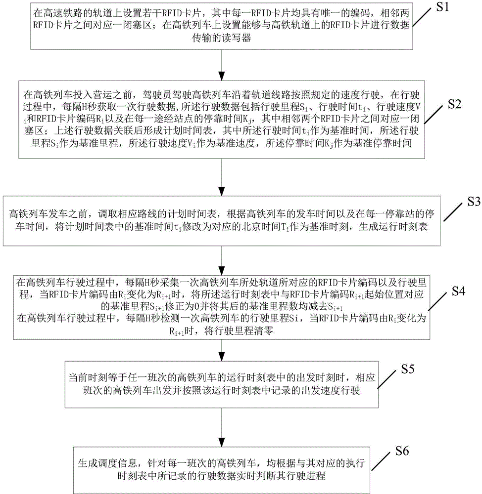
[0072] like figure 1 As shown, this embodiment provides a high-speed rail scheduling method that can be accurate to seconds when the stop time changes, such as figure 1 and figure 2 shown, including the following steps:

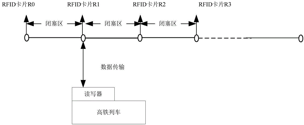
[0073] S1: Set several RFID cards on the track of the high-speed railway, where each RFID card has a unique code, and there is a blockage area between two adjacent RFID cards. Set up a reader on the high-speed rail train that can perform data transmission with the RFID card on the high-speed rail track.

[0074] S2: Generate planning schedule

[0075] Before the high-speed rail train is put into operation, the driver drives the high-speed rail train along the track line at a prescribed speed. During the driving process, the driving data is obtained every H seconds. The driving data includes the mileage S i , travel time t i , driving speed V i and RFID card code R iAnd the stop time K at each passing station j , wherein there is a blocking area betwe...

Embodiment 2

[0122] This embodiment provides a high-speed rail dispatching system that can be accurate to seconds when the stop time changes, such as Image 6 shown, including:

[0123] RFID cards are set on high-speed railway tracks, each RFID card has a unique code, and there is a blockage area between two adjacent RFID cards.

[0124] The reader is set on the high-speed rail train, and it can perform data transmission with the RFID card on the high-speed rail track.

[0125] Planned timetable generation module: before the high-speed rail train is put into operation, the driver drives the high-speed rail train to run at a prescribed speed along the track line. During the running process, the driving data is obtained every H seconds, and the driving data includes driving Mileage S i , travel time t i , driving speed V i and RFID card code R i And the stop time K at each passing station j , wherein there is a blocking area between two adjacent RFID cards. The above-mentioned travel ...


PUM


Abstract

The invention provides a high-speed railway scheduling method and system realizing the station dwell time change accurate to the second. Whether a running schedule needs to be regulated or not can be determined according to the station dwell time of each high-speed railway train passing in a passing station, the running schedule can also be corrected in time even when the station dwell time change value exceeds the set threshold range, and in addition, the high-speed railway train is enabled to run according to the corrected running schedule in a way of being accurate to the second. In addition, an RFID (radio frequency identification) technology is adopted in the technical scheme, the position positioning precision is improved, and when the current mileage of the high-speed railway train is not identical to the reference mileage corresponding to the current moment in the running schedule, the effect of reminding a driver of the running speed to realize the coincidence with the reference mileage of the running schedule in the preset time can be achieved. After the current mileage of the high-speed railway train is identical to the reference mileage specified in the running schedule, the effect of reminding the driver of the running speed for continuously maintaining the coincidence state in future can also be achieved.

Description

technical field [0001] The invention relates to the technical field of high-speed rail train dispatching, in particular to a high-speed rail dispatching method and system that can be accurate to seconds when the stop time changes. Background technique [0002] With the rapid development of society, the exchanges between cities are becoming more and more frequent. In order to shorten the travel time between cities, my country has carried out large-scale high-speed railway construction and put it into operation. How to ensure the safe and punctual operation of high-speed railways has aroused people's height focus on. [0003] At present, the train operation dispatching system of high-speed railway is dispatched by adopting the principle of automatic block partition of traditional railway. The so-called block partition is to use the track circuit to separate each section of track, and each section of track forms a block partition. Install a signal light or a virtual signal lig...

Claims


Application Information

Patent Timeline
IPC IPC(8): B61L23/16B61L27/04
Inventor 姜廷顺邱运邦李萌林拥军邹难栗红强
Owner BEIJING E HUALU INFORMATION TECH
Why Eureka
Try Eureka