Anti-collision bicycle handlebar

A bicycle and handlebar technology, applied in the field of anti-collision bicycle handlebars, can solve problems such as overturning accidents of bicycles and cyclists, bending of bicycle handlebars, etc., and achieve the effects of avoiding overturning of people and vehicles, speeding up exit speed, and improving reliability.

Active Publication Date: 2015-05-06
南通市华夏时丽网络科技服务有限公司
View PDF4 Cites 0 Cited by
  • Summary
  • Abstract
  • Description
  • Claims
  • Application Information

AI Technical Summary

Problems solved by technology

After investigation, it was found that most of the bicycles that overturned due to the impact of the electric vehicle overtaking at the rear were often hit or scratched by the electric vehicle to the handlebar on one side of the bicycle. When the electric bicycle comes from the rear, when it is hit suddenly from behind, the bicycle handle will be bent sharply, causing the bicycle and the rider to overturn.

Method used


Image

  • Anti-collision bicycle handlebar
  • Anti-collision bicycle handlebar
  • Anti-collision bicycle handlebar

Examples


Embodiment 1

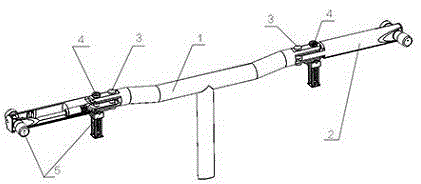
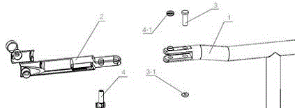
[0025] Such as figure 1 As shown, an anti-collision bicycle handle is characterized in that: it is composed of an inner section 1 and an outer section 2 that is respectively connected to the two ends of the inner section 1 in rotation, and an anti-rotation pin 4 is also provided at the rotation connection. Between the outer end of the outer section 2 and the anti-rotation pin 4, a potential energy pin-opening mechanism 5 for opening the anti-rotation pin 4 is provided.

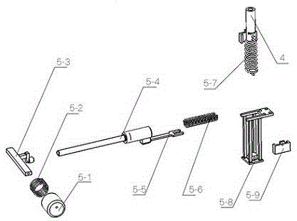
[0026] The potential energy unlocking mechanism 5 includes an impact activation mechanism, a rebound transmission mechanism and an unlocking device.

[0027] The impact activation mechanism includes an impact receiving cap 5-1, and an activation rod 5-3 fixedly connected with the impact receiving cap 5-1; the outer end side of the outer section 2 has a hole, and the impact driving mechanism Insert the outer section 2 through said hole.

[0028] The transmission mechanism is a rebound push rod 5-4, one end of...

Embodiment 2

[0032] On the basis of Embodiment 1, a return spring 5-2 is provided between the impact receiving cap 5-1 and the outer section 2.

[0033] Beneficial effects of this embodiment: after the impact is eliminated, the return spring automatically restores the mechanism to the initial state, as long as the outer joint is reset and the anti-rotation pin is installed in place, the restoration can be realized, and the operation is convenient.

Embodiment 3

[0035] On the basis of Embodiment 1, a pull-down elastic mechanism is provided below the anti-rotation pin 4, including a mounting frame 5-8 composed of four vertical rods, and one end is fixedly connected to the bottom of the mounting frame 5-8, and the other end is connected to the bottom of the mounting frame 5-8. The pull-down spring 5-7 that anti-rotation pin 4 is fixedly connected.

[0036] The beneficial effect of this embodiment is that: after the clamping plate used to fix the anti-rotation pin is opened, under the joint action of its own gravity and the pull-down elasticity, the anti-rotation pin will be pulled out from the pin hole at an accelerated rate, which improves the locking performance of the pin. agility.


PUM


Abstract

The invention discloses an anti-collision bicycle handlebar. The anti-collision bicycle handlebar is characterized by being composed of an inner joint (1) and outer joints (2) which are rotationally connected with the two ends of the inner joint (1) respectively, the rotational joints are further provided with anti-rotation pins (4), and potential energy pin starting mechanisms used for starting the anti-rotation pins (4) are arranged between the outer ends of the outer joints (2) and the anti-rotation pins (4). The potential energy pin starting mechanisms (5) comprise impact starting mechanisms, bounce transmission mechanisms and pin starting mechanisms. The anti-collision bicycle handlebar has the advantages that the energy unloading of the impact, from the back, on the bicycle handlebar is achieved, capsizing of a bicycle and a person after the impact is avoided, and the riding safety is guaranteed.

Description

technical field [0001] The invention relates to a bicycle component, in particular to an anti-collision bicycle handle. Background technique [0002] The traditional manpower pedal bicycle handle is an integral in-line handle made of a steel pipe. This handle has simple and firm structure, reliable steering performance, convenient processing and low cost. With the advancement of my country's urbanization process and the popularization of electric bicycles, there are more and more accidents where bicycles scratch or even collide with faster electric bicycles on the bicycle lanes in cities, especially in the case of electric bicycles whose speed exceeds the standard. In flooded areas, there is a greater chance of accidents in which bicycles are hit and overturned by electric bicycles, causing injuries to riders. In general, when a human-powered bicycle rider encounters an electric bicycle galloping ahead, the rider can rotate the bicycle handle in time to change the direction...

Claims


Application Information

Patent Timeline
Patent Type & Authority Applications(China)
IPC IPC(8): B62K21/14
CPCB62K21/14B62K21/16
Inventor 郭浣华章启迪陈丽娟
Owner 南通市华夏时丽网络科技服务有限公司
Why Eureka
Try Eureka