
Assembly line mechanism

An assembly line and waterline technology, applied in the direction of conveyors, conveyor objects, mechanical conveyors, etc., can solve problems affecting the quality of parts, affecting work efficiency, and the part number of parts cannot be determined, so as to prevent product mistakes and run smoothly. , the effect of preventing hard impact

Active Publication Date: 2015-05-06
BOZHON PRECISION IND TECH CO LTD
View PDF4 Cites 28 Cited by
  • Summary
  • Abstract
  • Description
  • Claims
  • Application Information

AI Technical Summary

Problems solved by technology

[0002] In the production or assembly workshop, etc., when the parts are operated, the parts are generally transported through the assembly line, and the assembly line mechanism of the prior art is only the driving device to drive the conveyor belt forward, and the carrier moves forward under the action of the conveyor belt. Whether there is a carrier on the assembly line during the moving process cannot be detected, the part number of the part on the carrier cannot be determined, and whether the position of the part is correct cannot be detected. Sometimes the carrier needs to be separated from the conveyor belt to operate the part. When operating the parts, the carrier needs to be stationary, but the assembly line of the prior art cannot realize the above functions, resulting in unexpected situations in the subsequent processing of the parts, which not only affects the work efficiency, but also affects the quality of the parts

Method used


Image

  • Assembly line mechanism
  • Assembly line mechanism
  • Assembly line mechanism

Examples


Embodiment Construction

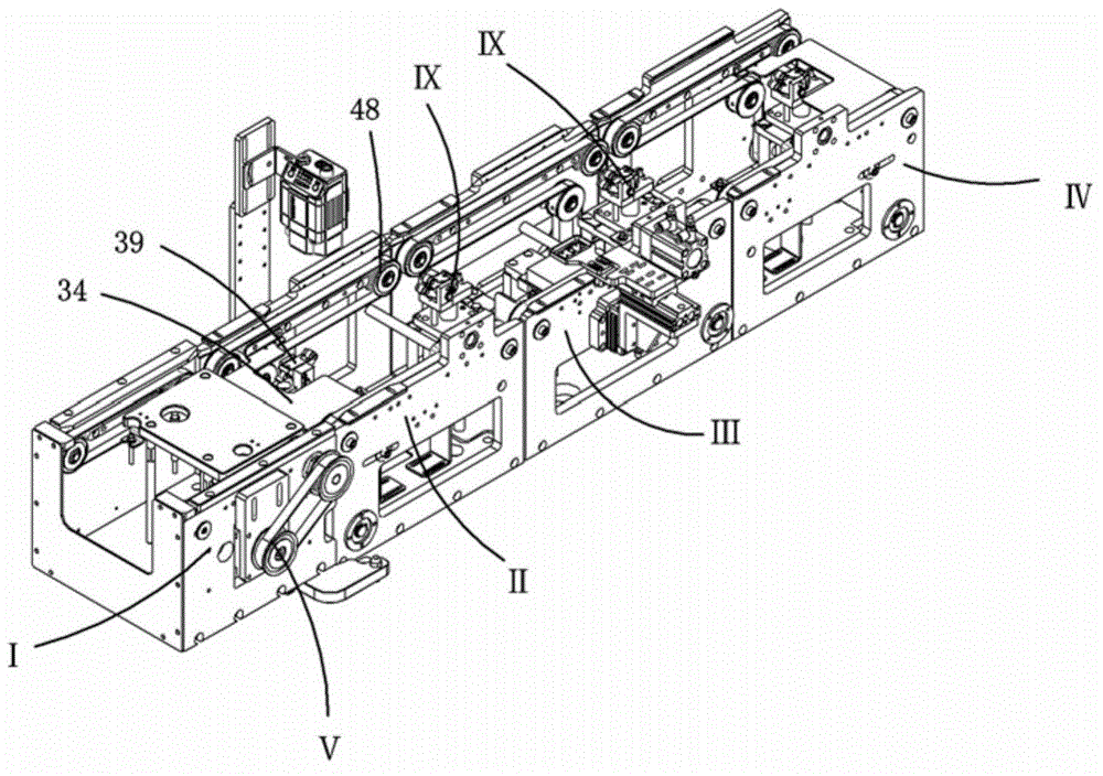
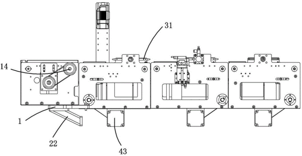
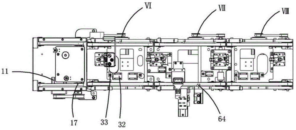
[0036] Examples, see attached Figure 1-9 , an assembly line mechanism, which includes sequentially connected feed assembly line mechanism Ⅰ, first assembly line mechanism Ⅱ, second assembly line mechanism Ⅲ and discharge assembly line mechanism Ⅳ, the feed assembly line mechanism includes a feed installation plate 1, a feed Base plate 2, feed front side plate 3, feed rear side plate 4 and feed drive device V, the feed base plate is installed on the feed installation plate, and the front and rear sides of the feed base plate are respectively equipped with feed The front side panel and the feeding rear side panel, the connection column between the feeding front side panel and the feeding rear side panel is strengthened and fixed to ensure the stability of the whole mechanism; the feeding front side panel and the feeding rear side panel A feed driving device is installed on the top, and a feed pallet 6 is installed on the feed bottom plate through four feed pillars 5, and the fe...


PUM


Abstract

The invention relates to an assembly line mechanism, which comprises a feeding assembly line mechanism, a first assembly line mechanism, a second assembly line mechanism and a discharge assembly line mechanism which are connected in sequence; the feeding assembly line mechanism is used for feeding; the first assembly line mechanism can be used for stopping a carrier, and the carrier stops moving; scanning is performed through a bar-code scanner, and the number of an electronic part on the carrier is recorded; the second assembly line mechanism can be used for separating the carrier from conveying belts and stopping the carrier moving forward, and after being lifted, the carrier can be kept level; then, the part is put on the carrier through a mechanical arm, and after the part is put, a pressure plate of a pressure mechanism is driven under the drive of a drive air cylinder and a lift air cylinder to press the part, and detection is performed on the part; after the detection is finished, the pressure mechanism shifts out, a push rod retreats, and the carrier goes on moving forward for transportation until the discharge of the discharge assembly line mechanism. According to the assembly line mechanism disclosed by the invention, all sections of assembly lines are separately arranged, and operation can be performed on a product at each work section; the assembly lines of the assembly line mechanism are steady in operation, and are convenient for performing the operation on the part.

Description

Technical field: [0001] The invention relates to the field of assembly line equipment, and more specifically relates to a mechanism capable of detecting the position of a carrier, determining the part number on the carrier and allowing the carrier to leave the assembly line. Background technique: [0002] In the production or assembly workshop, etc., when the parts are operated, the parts are generally transported through the assembly line, and the assembly line mechanism of the prior art is only the driving device to drive the conveyor belt forward, and the carrier moves forward under the action of the conveyor belt. Whether there is a carrier on the assembly line during the moving process cannot be detected, the part number of the part on the carrier cannot be determined, and whether the position of the part is correct cannot be detected. Sometimes the carrier needs to be separated from the conveyor belt to operate the part. When operating the parts, the carrier needs to b...

Claims


Application Information

Patent Timeline
Patent Type & Authority Applications(China)
IPC IPC(8): B65G37/00B65G43/00B65G47/88
Inventor 吕绍林汪炉生代飞李忠张泽庞
Owner BOZHON PRECISION IND TECH CO LTD
Learn More