
Electronic expansion valve control method and device

A technology of an electronic expansion valve and a control method, which is applied in the control field and can solve the problems that the reliability and energy efficiency of the system cannot be guaranteed.

Active Publication Date: 2017-05-10
GREE ELECTRIC APPLIANCES INC
View PDF6 Cites 0 Cited by
  • Summary
  • Abstract
  • Description
  • Claims
  • Application Information

AI Technical Summary

Problems solved by technology

[0005] The main purpose of the present invention is to provide a control method and device for an electronic expansion valve to solve the problem that the single-parameter control scroll unit system in the prior art cannot guarantee the reliability and energy efficiency of the system under any working conditions

Method used


Image

  • Electronic expansion valve control method and device
  • Electronic expansion valve control method and device
  • Electronic expansion valve control method and device

Examples


Embodiment Construction

[0025] It should be noted that, in the case of no conflict, the embodiments in the present application and the features in the embodiments can be combined with each other. The present invention will be described in detail below with reference to the accompanying drawings and examples.

[0026] In order to enable those skilled in the art to better understand the solution of the present application, the technical solution in the embodiment of the application will be clearly and completely described below in conjunction with the accompanying drawings in the embodiment of the application. Obviously, the described embodiment is only It is an embodiment of a part of the application, but not all of the embodiments. Based on the embodiments in this application, all other embodiments obtained by persons of ordinary skill in the art without creative efforts shall fall within the scope of protection of this application.

[0027] It should be noted that the terms "first" and "second" in ...


PUM


Abstract

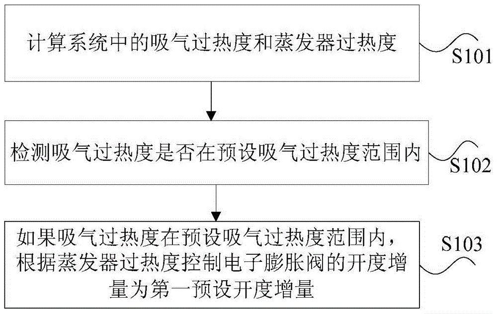
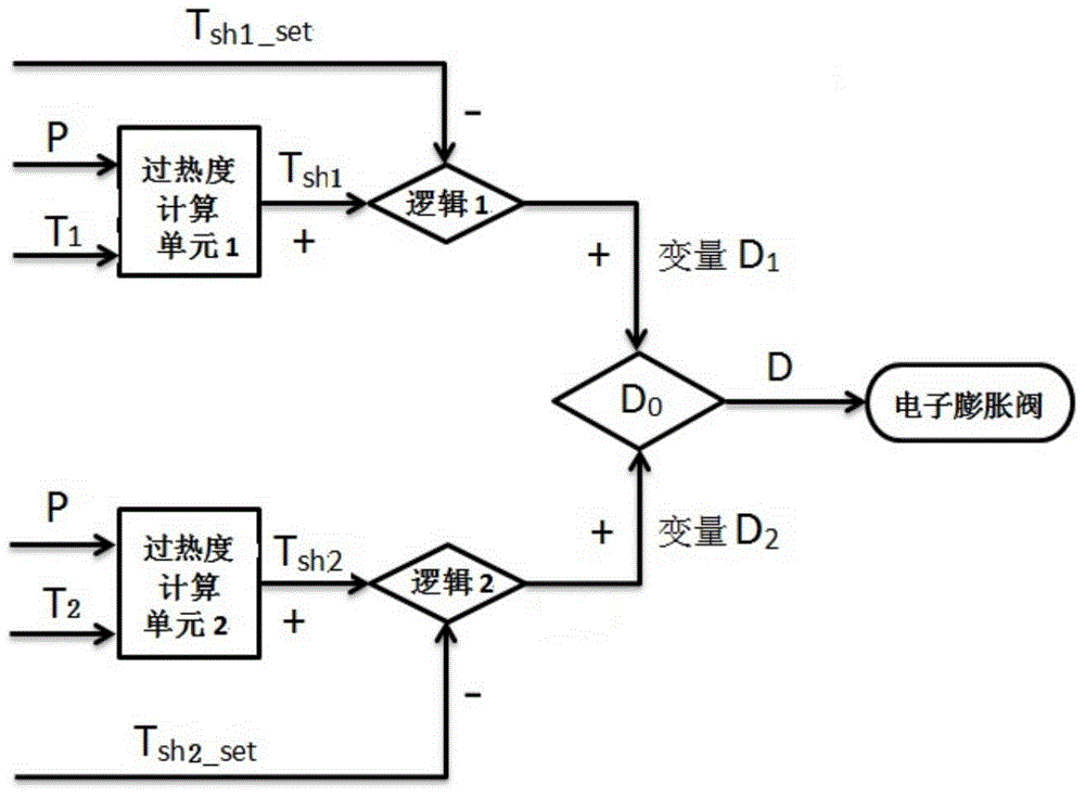
The invention discloses a control method and a control device for an electronic expansion valve. The method includes the following steps: sucked vapor superheat degree and evaporator superheat degree in a system are calculated, wherein the system is a system comprising the electronic expansion valve; whether the sucked vapor superheat degree is within a preset sucked vapor superheat degree range is detected; if the sucked vapor superheat degree is within the preset sucked vapor superheat degree range, the opening degree increment of the electronic expansion valve is controlled at a first preset opening degree increment according to the evaporator superheat degree. The invention solves the problem in the prior art that a single-parameter-controlled scroll unit system cannot ensure reliability and energy efficiency under any working conditions.

Description

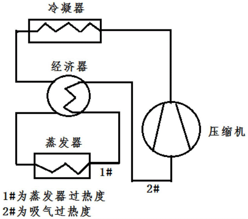
technical field [0001] The invention relates to the field of control, in particular to a control method and device for an electronic expansion valve. Background technique [0002] Avoiding liquid shock is one of the important factors in the design of the scroll unit system. Usually, methods such as adding gas-liquid separator, adding oil heating and economizer are adopted. The basic principles of these three schemes are different: Heating to avoid liquid shock at the moment of compressor start-up; the gas-liquid separator is mainly to separate liquid and gaseous refrigerant to avoid liquid shock to the compressor; the economizer is to increase the overheating of the suction The content of liquid refrigerant at the gas port, so as to avoid liquid shock. [0003] For refrigeration systems using economizers, the economizers are selected according to the worst superheat conditions, and the heat transfer of economizers varies greatly under different working conditions. When the...

Claims


Application Information

Patent Timeline
Patent Type & Authority Patents(China)
IPC IPC(8): F25B49/02
CPCF25B49/02F25B2500/18F25B2600/2513
Inventor 樊启迪杨二玲姜国璠周江峰余聪
Owner GREE ELECTRIC APPLIANCES INC
Learn More