Detection wheel with directionality and method for detecting running speed and running direction of vehicle at same time

A technology for detecting wheel and directionality, applied to devices using electric/magnetic methods, speed/acceleration/shock measurement, measuring devices, etc., can solve problems such as unresolved safety hazards

Inactive Publication Date: 2015-05-06
浙江长兴德纳克斯动力科技有限公司
View PDF5 Cites 9 Cited by
  • Summary
  • Abstract
  • Description
  • Claims
  • Application Information

AI Technical Summary

Problems solved by technology

[0005] Although the driving direction of the vehicle can be calculated through the vehicle positioning system, due to the problems of positioning accuracy, response time, signal strength, communication speed, etc., the above safety hazards cannot be solved at present.

Method used


Image

  • Detection wheel with directionality and method for detecting running speed and running direction of vehicle at same time
  • Detection wheel with directionality and method for detecting running speed and running direction of vehicle at same time
  • Detection wheel with directionality and method for detecting running speed and running direction of vehicle at same time

Examples


Embodiment 1

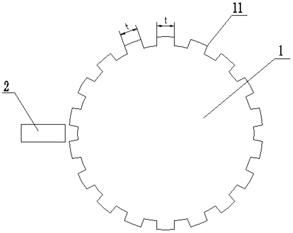
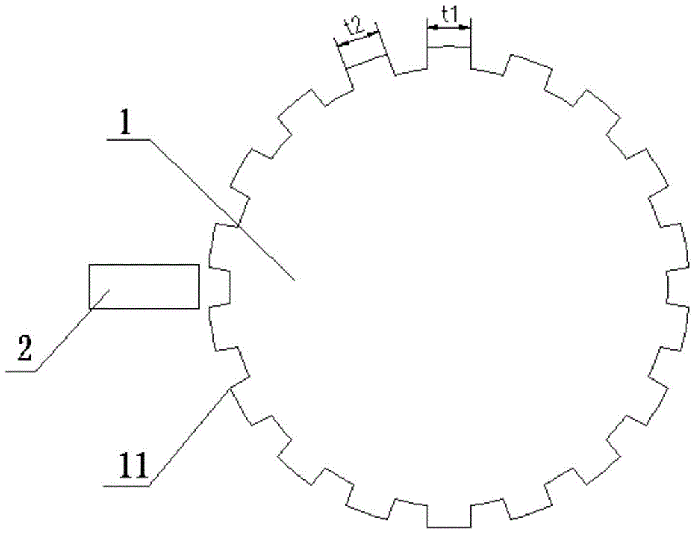
[0033] Such as image 3 with Figure 4 As shown, a directional detection wheel 1 includes at least four detection gear teeth 11, the detection gear teeth are arranged at intervals on the circumference of the detection wheel, with the forward direction of the vehicle as the positive direction, two adjacent The distance between the front ends or the rear ends of each of the detection gear teeth is equal, and with the front end or the rear end as the reference, the tooth thicknesses of the detection gear teeth are distributed in an arithmetic sequence in order, that is, the first The tooth thickness of the detected gear teeth is the smallest, the tooth thickness of the second detected gear tooth is larger than that of the first detected gear tooth, the tooth thickness of the third detected gear tooth is larger than that of the second detected gear tooth, So on and so forth. In this embodiment, the forward direction of the entire vehicle is taken as the forward direction, and ac...

Embodiment 2

[0035] A detection wheel 1 with directionality, the detection teeth on the detection wheel are divided into two or more groups of tooth combinations with the same number of detection teeth in sequence, and the detection teeth of the tooth combination are arranged at intervals between the On the circumference of the detection wheel, the tooth thicknesses of the detection teeth in each group of tooth combinations are distributed in an arithmetic sequence in order, and the number of detection teeth in each group of tooth combinations is not less than three.

[0036] During specific implementation, the detection gear teeth of the detection wheel can be divided into two or more groups in sequence, the number of detection gear teeth in each group is the same, and the tooth thickness of each detection gear tooth in the group is distributed in an arithmetic sequence in order, that is The tooth thickness of the first detection gear tooth is the smallest, the tooth thickness of the secon...


PUM


Abstract

The invention discloses a detection wheel with directionality and a method for detecting running speed and running direction of a vehicle at the same time. Pulse detection is performed on the detection wheel through a rotating speed sensor, and with the help of analysis and calculation of a control system, rotating speed and rotating direction of the detection wheel can be acquired at the same time, so that actual running rotating speed and advancing direction of the vehicle can be acquired at the same time. Actual traveling direction of the vehicle can be detected only by changing detection wheel teeth of an existing detection wheel, so that the problem that the rotating speed sensor can only acquire rotating speed from the detection wheel and cannot determine direction in the prior art is solved, the safety problem caused by the fact that the actual traveling direction of the vehicle is opposite to needed moving direction is solved, and potential safety hazards in running of the vehicle are eliminated.

Description

technical field [0001] The invention relates to a detection structure and a detection method for vehicle running conditions, in particular to a directional detection wheel and a method for simultaneously detecting vehicle running speed and direction. Background technique [0002] In the current speed detection of automobiles, the speed of the whole vehicle is mainly calculated by detecting the speed of the detection wheel (or signal wheel) through the speed sensor. see figure 1 with figure 2 , the working principle of the current detection wheel is: the same detection gear teeth are evenly arranged on the detection wheel 1, and the tooth thickness t of all teeth is equal. Whenever a detection gear tooth passes the speed sensor 2, the speed sensor outputs a pulse , the starting point of the pulse is the point where the front end of the detection gear tooth enters the detection area of ​​the speed sensor, and the end point of the pulse is the point where the tail end of the...

Claims


Application Information

Patent Timeline
Patent Type & Authority Applications(China)
IPC IPC(8): G01P3/50G01P13/00
Inventor 袁一卿涂乐平张寅伍国强何祥延张秋雨刘广辉
Owner 浙江长兴德纳克斯动力科技有限公司
Why Eureka
Try Eureka