Optical device

A technology for optical devices and optical components, which is applied in the directions of optics, electromechanical devices, projection devices, etc., can solve the problems of changing the shape, and it is difficult to eliminate the reduction of the curvature of the central part and the curvature of the central part.

Inactive Publication Date: 2015-05-06
SANKYO SEIKI MFG CO LTD
View PDF9 Cites 3 Cited by
  • Summary
  • Abstract
  • Description
  • Claims
  • Application Information

AI Technical Summary

Problems solved by technology

[0005] However, in the techniques described in Patent Documents 1 and 2, since a load is applied to the center portion or end portion of a flat plate-shaped optical member to bend it, even when it is bent in an arc shape, for example, there is a center The problem that the curvature of the part becomes smaller and cannot be bent into the desired shape with high precision
In addition, in the techniques described in Patent Documents 1 and 2, since the flat optical member is fixed so as to maintain a curved state, there is a problem that the shape cannot be changed according to the usage situation.
[0006] In addition, as shown in Fig. 19 (a) and Fig. 19 (b), it is conceivable to join the back plate 9 made of a steel plate with a constant thickness on the entire back side of the optical component 2, but even if such a back plate 9 is joined, it is very difficult. It is difficult to eliminate the problem that the curvature of the central part becomes smaller when bending as shown in Fig. 19(c)

Method used


Image

  • Optical device
  • Optical device
  • Optical device

Examples


Embodiment 1

[0084] The backside of the optic 2 is bonded by Figure 3(a) to Figure 3(c) The reinforced part 3B is formed of zinc steel sheet as shown. The bending method is as described later with reference to Figure 15(a), Figure 16(a), Figure 16(b) and Figure 17(a), Figure 17(b) along the X direction (first direction) The way the load is applied.

Embodiment 2

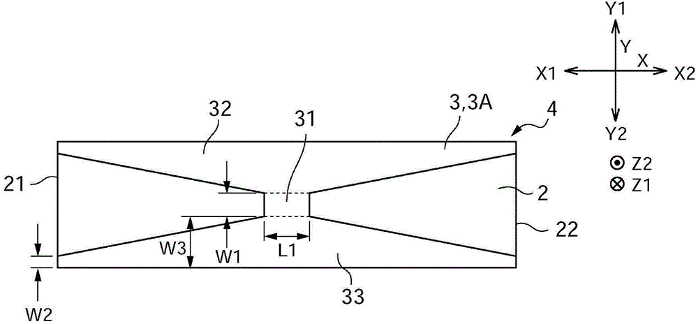
[0086] The backside of the optic 2 is bonded by Figure 2(a) to Figure 2(c) The reinforced member 3A is formed of zinc steel sheet as shown. The bending method is as described later with reference to Figure 15(a), Figure 16(a), Figure 16(b) and Figure 17(a), Figure 17(b) along the X direction (first direction) The way the load is applied.

Embodiment 3

[0088] The back plate 9 formed by the quadrangular zinc steel plate is bonded to the back of the optical part 2 (refer to Figure 19(a) to Figure 19(c) ), and bonded at the back of the back plate 9 by Figure 2(a) to Figure 2(c) The reinforced member 3A is formed of zinc steel sheet as shown. The bending method is as described later with reference to Figure 15(a), Figure 16(a), Figure 16(b) and Figure 17(a), Figure 17(b) along the X direction (first direction) The way the load is applied.


PUM


Abstract

An optical device may include a flat optical member; a reinforcement member which is bonded to a back side of the optical member and demonstrates stronger rigidity in a center area thereof than two side portions thereof when curved in a thickness direction in a first direction within an in-plane direction; and a driving device which switches a shape of the optical member together with the reinforcement member between a flat state and a curved state in which the optical member is curved in the first direction.

Description

technical field [0001] The present invention relates to an optical device capable of using a planar optical member in a bent state. Background technique [0002] Flat-shaped optical components such as mirrors, organic electroluminescent display panels, and liquid crystal display panels sometimes become curved due to the fact that their base materials are made of metal plates, glass substrates, and the like. For example, a technique of bending a liquid crystal panel in response to usage conditions has been proposed (see Patent Documents 1 and 2). [0003] Patent Document 1: Japanese Patent Application Laid-Open No. 6-3650 [0004] Patent Document 2: Japanese Patent Application Laid-Open No. 10-268790 [0005] However, in the techniques described in Patent Documents 1 and 2, since only a load is applied to the center portion or end portion of a flat plate-shaped optical member to bend it, even when it is bent in an arc shape, for example, there is a center There is a proble...

Claims


Application Information

Patent Timeline
Patent Type & Authority Applications(China)
IPC IPC(8): G09F9/30G09F9/35A47G1/02H01L27/32H02K7/10
CPCA47G1/02G02F1/1303G09F9/30G09F9/35H02K7/10G02F1/133302H10K59/00G02B26/0825G02B27/00G02F1/1333H05K7/00G02F1/133608G03B21/56G02F1/133305
Inventor 吉川伸一安藤正明佐藤恒雄
Owner SANKYO SEIKI MFG CO LTD
Why Eureka
Try Eureka