Passive Receiver for Wireless Power Transmission

A wireless power and receiver technology, applied in the direction of output power conversion devices, antennas, loop antennas, etc., can solve the problem of reducing charging efficiency

Active Publication Date: 2019-02-12
QUALCOMM INC
View PDF5 Cites 0 Cited by
  • Summary
  • Abstract
  • Description
  • Claims
  • Application Information

AI Technical Summary

Problems solved by technology

This low charging resistance reduces charging efficiency

Method used


Image

  • Passive Receiver for Wireless Power Transmission
  • Passive Receiver for Wireless Power Transmission
  • Passive Receiver for Wireless Power Transmission

Examples


Embodiment Construction

[0034] The word "exemplary" herein means "serving as an example, instance, or illustration." Any embodiment described herein as "exemplary" is not necessarily to be construed as preferred or advantageous over other embodiments.

[0035] It is intended that the detailed description set forth below in conjunction with the accompanying drawings be a description of exemplary embodiments of the invention and not be intended to represent the only embodiments in which the invention may be practiced. The term "exemplary" is used throughout this description to mean "serving as an example, instance, or illustration" and should not necessarily be construed as preferred or advantageous over other exemplary embodiments. The detailed description includes specific details for the purpose of providing a thorough understanding of exemplary embodiments of the invention. It will be apparent to those skilled in the art that the exemplary embodiments of the invention may be practiced without thes...


PUM


Abstract

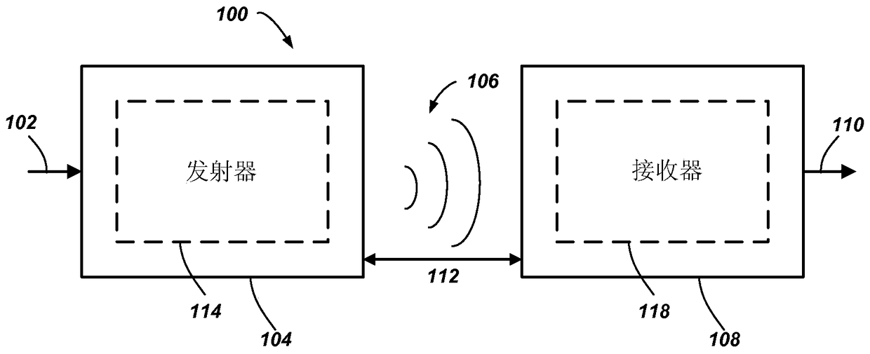
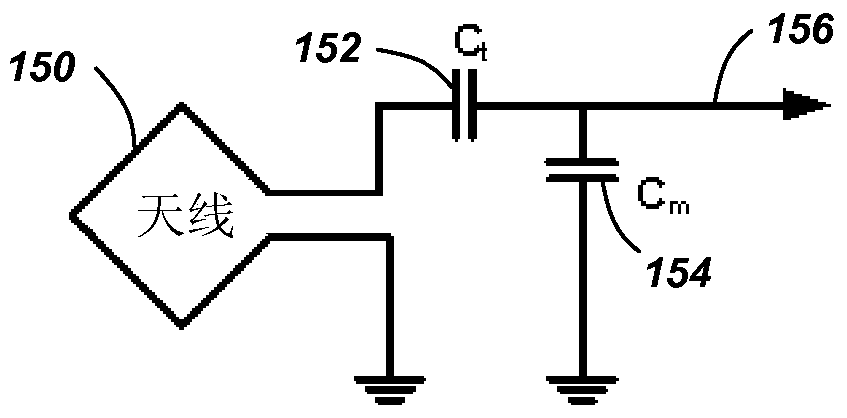
The present invention relates to passive receivers for wireless power transmission. Exemplary embodiments are directed to wireless power transfer. The wireless power transmit receiver includes a receive antenna including a parallel resonator configured to resonate in response to a magnetic near field and to couple wireless power from the magnetic near field. The receiver further includes a passive rectifier circuit coupled to the parallel resonator. The passive rectifier circuit is configured to transform a load impedance to the parallel resonator.

Description

[0001] Information about divisional applications [0002] This case is a divisional application. The parent case of this divisional case is an invention patent application with the application date of August 25, 2009, the application number 200980132967.2, and the invention title "Passive Receiver for Wireless Power Transmission". [0003] Claim of priority under 35 U.S.C. §119 [0004] This application claims priority under 35 U.S.C. § 119(e): [0005] U.S. Provisional Patent No. 61 / 091,684, entitled "PASSIVE DIODE RECTIFIER RECEIVERS FOR WIRELESS POWERING AND CHARGING OF ELECTRONIC DEVICES," filed August 25, 2008 application, the disclosure of which is hereby incorporated by reference in its entirety. [0006] U.S. Provisional Patent No. 61 / 117,937, filed November 25, 2008, entitled "PASSIVE DIODE RECTIFIER RECEIVERS FOR WIRELESS POWERING AND CHARGING OF ELECTRONIC DEVICES" application, the disclosure of which is hereby incorporated by reference in its entirety. [000...

Claims


Application Information

Patent Timeline
Patent Type & Authority Patents(China)
IPC IPC(8): H02J50/20H02J5/00H01Q1/22H01Q7/00
CPCH01Q1/2225H01Q7/00H02J7/00308H02J50/12H02M1/12H02J50/80H02J50/20
Inventor 奈杰尔·P·库克卢卡斯·西贝尔汉斯彼得·威德默
Owner QUALCOMM INC
Why Eureka
Try Eureka