Material ejection mechanism

A material and material channel technology, applied in the field of material injection mechanism, can solve problems such as complex structure, lower production efficiency, and difficulty in realizing one-time material positioning of materials, so as to simplify the molding process, improve production efficiency, and simplify the assembly process.

Active Publication Date: 2015-05-06
GOERTEK INC
View PDF4 Cites 0 Cited by
  • Summary
  • Abstract
  • Description
  • Claims
  • Application Information

AI Technical Summary

Problems solved by technology

However, it is often encountered that the set spacing is small, or even smaller than the minimum outer diameter of the duct that can be used. At this time, if the material is blown out directly from the duct, it is difficult to realize the one-time positioning of the material; if the method of blowing out multiple times is used, it will be Complicate the structure and reduce production efficiency

Method used


Image

  • Material ejection mechanism
  • Material ejection mechanism
  • Material ejection mechanism

Examples


Embodiment 1

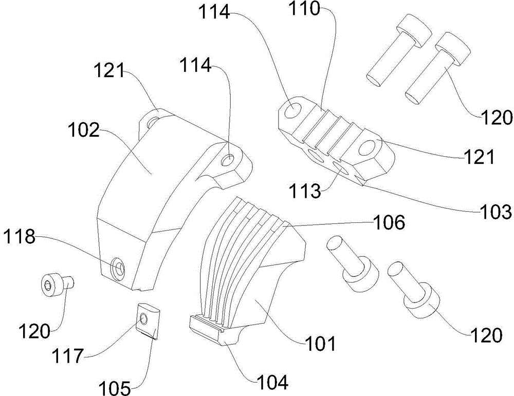
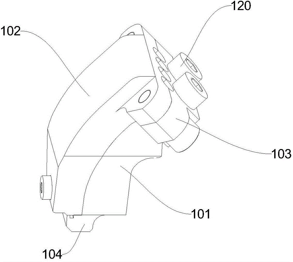
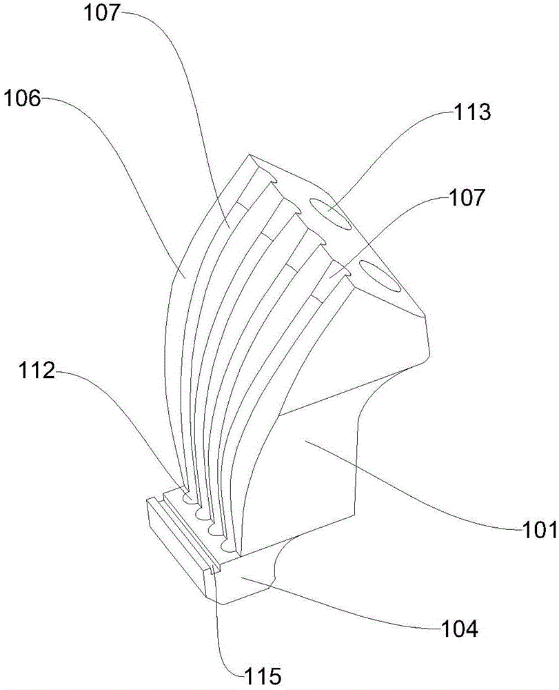
[0053] figure 1 It is an exploded view of the material injection mechanism in Embodiment 1 of the present invention, figure 2 is a schematic structural view of the material injection mechanism in Embodiment 1 of the present invention, image 3 It is a structural schematic diagram of the injection chamber in Embodiment 1 of the present invention, Figure 4 It is a perspective view of the injection chamber in Embodiment 1 of the present invention, Figure 5 is along Figure 4 A sectional view along line A-A, Figure 6 It is a structural schematic diagram of the docking bin in Embodiment 1 of the present invention, Figure 7 It is a perspective view of the docking bin in Embodiment 1 of the present invention, Figure 8 yes Figure 7 B direction view, Figure 9 It is a perspective view of the connector in Embodiment 1 of the present invention. Such as Figure 1 to Figure 9 As shown, Embodiment 1 of the present invention discloses a material injection mechanism, which inc...

Embodiment 2

[0064] Figure 10 It is the explosion diagram of the material injection mechanism in the second embodiment of the present invention, Figure 11 is a schematic structural view of the material injection mechanism in Embodiment 2 of the present invention, Figure 12 It is a perspective view of the injection chamber in Embodiment 2 of the present invention, Figure 13 is along Figure 12 A sectional view along line C-C, Figure 14 is a schematic structural diagram of the docking bin in Embodiment 2 of the present invention, Figure 15 It is a perspective view of the docking bin in Embodiment 2 of the present invention, Figure 16 yes Figure 15 D direction view, Figure 17 It is a perspective view of the connector in Embodiment 2 of the present invention. Such as Figure 10 to Figure 17 As shown, Embodiment 2 of the present invention discloses a material injection mechanism, which includes a conduit fixing part, a material channel part and an injection head connected in se...


PUM


Abstract

The invention discloses a material ejection mechanism comprising a guide pipe fixing portion, a material channel portion and an ejection head which are sequentially connected. A plurality of linear guide pipe grooves for fixing a material guide pipe are parallelly formed in the guide pipe fixing portion, a plurality of linear ejection holes in one-to-one correspondence to the guide pipe grooves are parallelly formed in the ejection head, the distance between every two ejection holes is shorter than that between every two guide pipe grooves, the material channel portion comprises an ejection bin and a butt joint bin, a first curved surface is arranged on the ejection bin, a plurality of first grooves with circular arc sections are parallelly distributed in the first curved surface along the bending direction of the curved surface and recessed into the first curved surface, a second curved surface matched with the first curved surface is arranged on the butt joint bin, a plurality of second grooves in one-to-one correspondence to the first grooves are formed in the second curved surface, and each first groove is in butt joint with the corresponding second groove to form a complete material channel. The material ejection mechanism has the advantages of simple structure and convenience in operation.

Description

technical field [0001] The invention relates to a tooling, in particular to a material injection mechanism. Background technique [0002] In the assembly of electronic parts, in the production process of transferring and positioning light and small solid materials (abbreviated as materials), such as springs and ball parts, it is sometimes necessary to use airflow to blow the materials out along the duct and blow them out according to the design Arrange them at a certain distance for the subsequent assembly process. However, it is often encountered that the set spacing is small, or even smaller than the minimum outer diameter of the duct that can be used. At this time, if the material is blown out directly from the duct, it is difficult to realize the one-time positioning of the material; if the method of blowing out multiple times is used, it will be Complicate the structure and reduce production efficiency. Contents of the invention [0003] In view of the above deficie...

Claims


Application Information

Patent Timeline
Patent Type & Authority Applications(China)
IPC IPC(8): H05K13/02
Inventor 闫向东
Owner GOERTEK INC
Why Eureka
Try Eureka