Hydraulic self-induced vibration subsoiler

A technology of self-excited vibration and subsoiler, applied to agricultural machinery and implements, applications, plows, etc., can solve the problems of poor consistency of tillage depth, large shaft length, discomfort, etc., to ensure consistency of tillage depth and reduce traction resistance Small, compact and simple effect

Inactive Publication Date: 2015-05-13
SHIHEZI UNIVERSITY
View PDF6 Cites 17 Cited by
  • Summary
  • Abstract
  • Description
  • Claims
  • Application Information

AI Technical Summary

Problems solved by technology

[0007] At present, the problem existing in the existing soil subsoiling machine is: the traction resistance of the soil subsoiling machine increases with the increase of the soil subsoiling depth, especially the current four-row subsoiling requires medium and high-power tractors to achieve, This increases the cost of subsoiling and fuel consumption, and because of the large size of the high-power tractor, it makes it difficult to turn the ground
At present, the production efficiency of the soil subsoiler is low and the soil will be compacted when the tractor enters the ground for many times. The vibration of the tractor causes the tractor to vibrate, which is easy to cause discomfort to the tractor driver. At present, the number of subsoiling rows and the subsoiling interval of the existing vibrating subsoiler are not easy to adjust, and the plowing depth consistency is poor

Method used


Image

  • Hydraulic self-induced vibration subsoiler
  • Hydraulic self-induced vibration subsoiler
  • Hydraulic self-induced vibration subsoiler

Examples


Embodiment 1

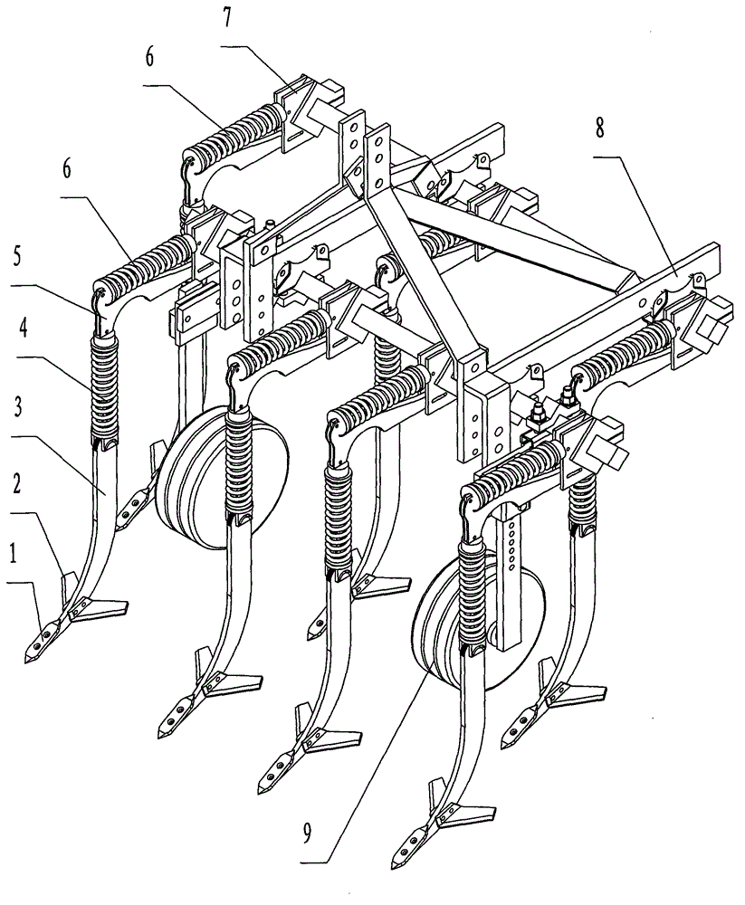
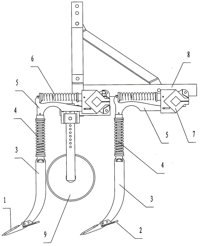
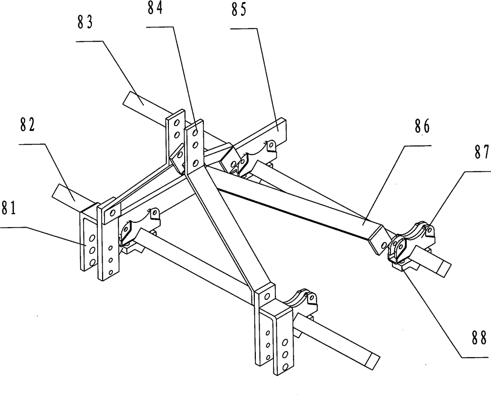
[0032] Embodiment 1: with reference to attached Figure 1-12, the present invention comprises frame 8 and subsoiling device, and described subsoiling device is arranged under frame 8, and described frame 8 is composed of suspension sub-board 81, front beam 82, rear beam 83, inclined draw bar 84, crossbeam 85. A transverse drawbar 86, a "U" groove fixing piece 87 and a "V" lock piece 88 are formed. The suspension sub-board 81 is connected to the beam 85, and the upper end of the inclined drawbar 84 is connected to the transverse The inner side of the upper end of the drawbar 86, the lower end of the transverse drawbar 86 is connected to the inner side of the suspension sub-board 81, the lower end of the inclined drawbar 84 is connected to the inner side of the crossbeam 85, and the crossbeam 85 is connected in the groove of the "U"-shaped groove fixture 87, "U" ""-shaped groove fixing piece 87 and "V"-shaped locking piece 88 embrace the front beam 82 and rear beam 83 and fasten...

Embodiment 2

[0033] Embodiment 2: The difference from Embodiment 1 is that the front beam 82 and the rear beam 83 of the frame 8 are arranged in alignment, and the subsoiling shovel is arranged symmetrically with the front four and the rear four. This setting is suitable for inter-plant subsoiling and crop growth period In addition, the subsoiling device can be arranged on the front beam 82, and the subsoiling device can be removed on the rear beam 83, and the rotary tiller can be installed to realize joint operation.


PUM


Abstract

The invention relates to a hydraulic self-induced vibration subsoiler. The hydraulic self-induced vibration subsoiler is characterized by comprising a machine frame and a subsoiling device, wherein the subsoiling device is arranged at the bottom of the machine frame, the machine frame is composed of suspension pair plates, a front beam, a rear beam, an inclined traction rod, a cross beam, a cross traction rod, U-shaped groove fixing pieces and V-shaped locking pieces, and the subsoiling device is composed of shovel points, shovel wings and shovel handles. According to the hydraulic self-induced vibration subsoiler, the stretch and retraction amount of vibration springs is controlled and adjusted through hydraulic oil, the embedded depths of all subsoiling shovels are effectively adjusted, in this way, the tilling depth consistency is guaranteed during subsoiling, and the overall vibration which causes discomfort of a driver of a tractor and the like and is generated due to inconsistency of shake of mechanisms of the subsoiler is reduced; compared with a non-vibration subsoiler and a one-way vibration subsoiler under the same condition, during work, the traction resistance is remarkably reduced; to sum up, the hydraulic self-induced vibration subsoiler can reduce resistance and save energy and is good in operation effect and high in adaptability.

Description

technical field [0001] The invention relates to a hydraulic self-excited vibration subsoiler. Background technique [0002] Soil subsoiling refers to the use of subsoilers to loosen and crush the plow substratum soil 5 to 15 cm below the plow layer, and to deepen the thickness of the loose soil layer. As an important technology of soil cultivation, subsoiling has attracted more and more attention at home and abroad. , due to long-term plowing or stubble removal operations, the bottom of the plowed soil rises and the cultivated layer becomes shallower. Finally, soil erosion intensifies and the soil gradually degrades. The more degraded the soil, the lower the income of farmers and the lower the production efficiency. Therefore, the deep soil The problem of pine has become an urgent problem to be solved for the increase of farmers' planting income. [0003] The first technology of soil subsoiling is: it can break the compaction of soil, and then deepen the plow layer. Soil su...

Claims


Application Information

Patent Timeline
Patent Type & Authority Applications(China)
IPC IPC(8): A01B13/08
Inventor 李霞汤明军李文春王维新郭金龙王志穷
Owner SHIHEZI UNIVERSITY
Why Eureka
Try Eureka