
Stop device for a portable machine tool

A technology of a hand-held machine tool and a stop device, which is applied in the direction of manufacturing tools, wood processing appliances, portable motorized circular saws, etc., and can solve the problem that the tool cannot be clamped or used in a moving part or a hand-held machine tool, depth stop The problem that the block cannot be easily clamped can reduce the risk of jamming and the risk of breaking

Inactive Publication Date: 2012-07-04
ROBERT BOSCH GMBH
View PDF6 Cites 5 Cited by
  • Summary
  • Abstract
  • Description
  • Claims
  • Application Information

AI Technical Summary

Problems solved by technology

To date, tools with a different number of carrying openings could not be clamped or used on the above-mentioned carrying parts or hand-held power tools
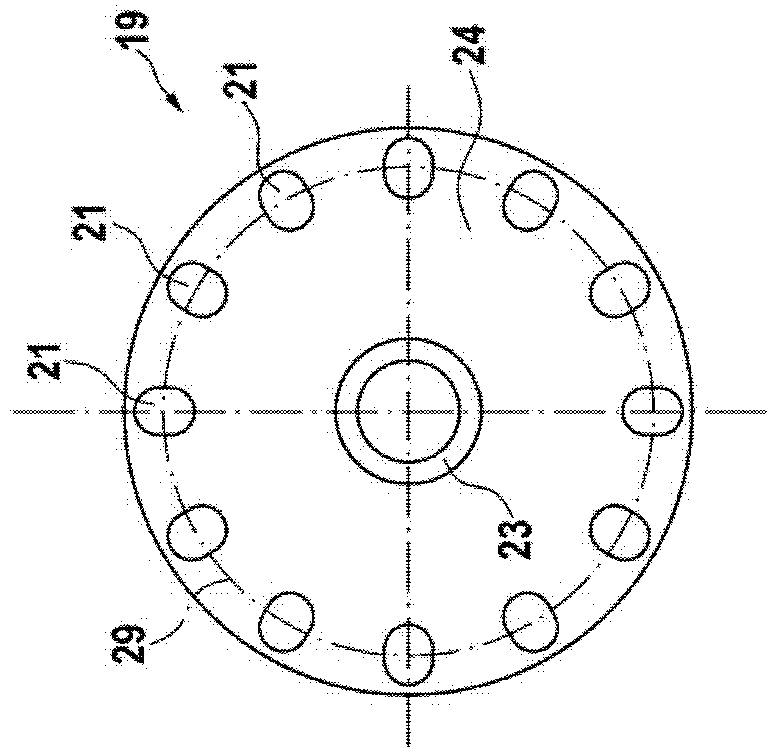
[0004] This also applies to the conventional, disc-shaped, flat depth stop according to DE 10 2008 001 234 A1, which cannot be easily clamped or used on the aforementioned driver with preferably twelve projections and which also Not suitable for bent knives

Method used


Image

  • Stop device for a portable machine tool
  • Stop device for a portable machine tool
  • Stop device for a portable machine tool

Examples


Embodiment Construction

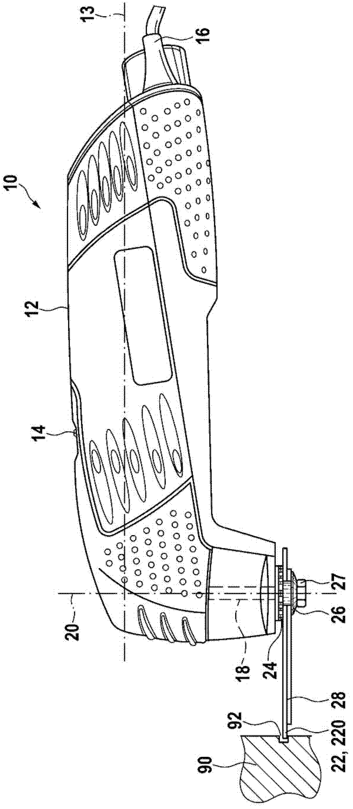
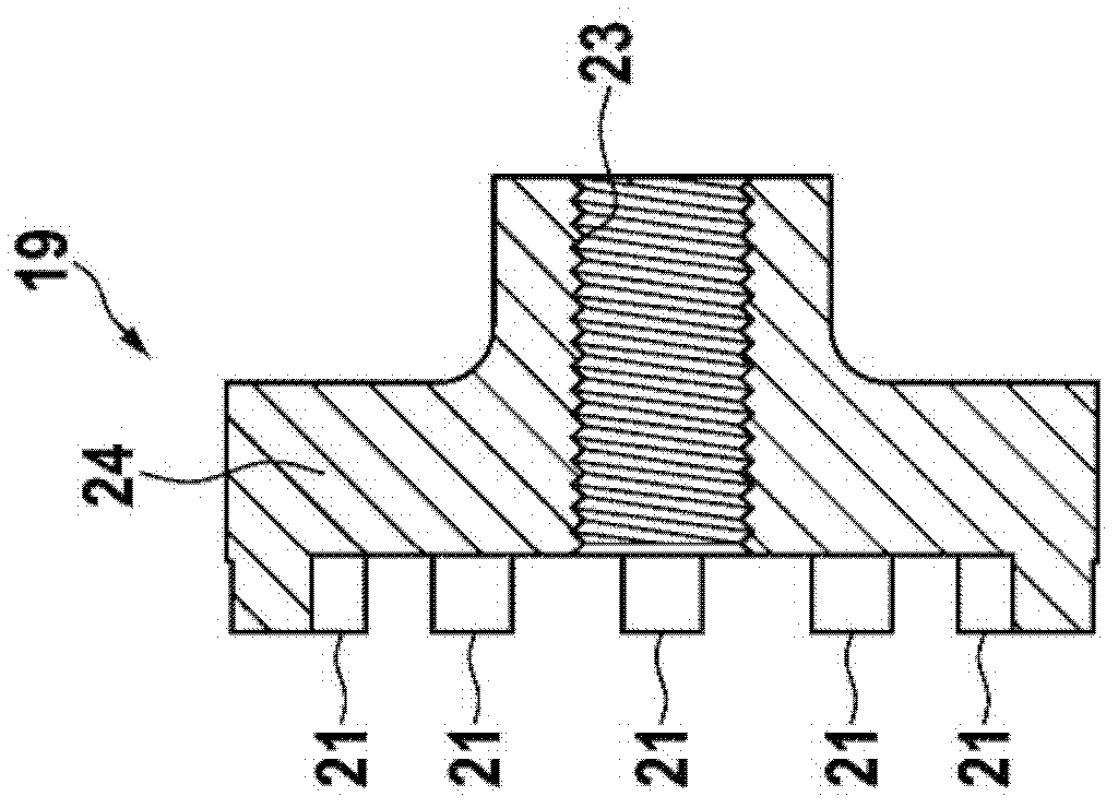
[0033] exist figure 1 The exemplary hand-held power tool 10 shown schematically in has an elongated housing 12 with a longitudinal axis 13, which carries on its upper side a device for switching on and off located in the housing 12. The switch button 14 of the not shown motor. The motor is connected via a cable 16 to a power supply or is fed directly from a storage battery. The motor transmits its motion to a driven shaft 18 with axis 20 , which is mounted at the front of the housing 12 . The axis 20 protrudes from the housing 12 at an angle, essentially at right angles, to the longitudinal axis 13 in this example and carries an inner flange 24 at its end, which simultaneously serves as the driver 19 .

[0034] The driven shaft 18 carries on its inner flange 24 a releasably clampable, oscillatingly drivable, substantially flat tool 22 which is configured as a flat, circular segment-shaped saw blade 22a and can be A fastening device in the form of a clamping screw 27 is cla...


PUM


Abstract

The invention relates to a stop device, particularly a depth stop (280), for a rotationally driven, particularly oscillatingly driven, chipping or cutting, round and / or angular disc shaped tool (22, 220) of a portable machine tool, particularly a saw blade, by means of which a cut (92) can be produced in a workpiece (90) in a chipping manner, comprising a disc-like means that is arranged axially adjacent to the tool (22, 220), preferably axially supported thereon, and exposes opposite the outer edge thereof (290) a certain part of the tool (22) for penetration into the cut (92) by a defined degree and prevents further penetration into the cut (92) beyond the defined degree, as soon as the edge (290) is supported on the tool (90). According to the invention, the disc-shaped tool (22, 220) is crucible-shaped and the stop device, particularly the depth stop (280), is also similarly designed so as to be precisely crucible-shaped, wherein the depth stop (280) enters a concave crucible-shaped region of the tool (22, 220) and / or vice versa, it receives the tool (22, 220) in an axially supporting manner in the concave crucible-shaped region thereof.

Description

technical field [0001] The invention relates to a stop device, in particular a depth stop, for a tool of a hand-held power tool according to the preamble of claim 1 or claim 9 and a hand-held power tool, in particular Hand-held machine tool with oscillating drive shaft. Background technique [0002] Hand-held power tools of this type are known to have a rotating, in particular oscillatingly driven, cutting or cutting, round and / or angular disk-shaped tool, in particular a saw blade, by means of which the workpiece can be cut The kerf is produced in a medium-cut manner, wherein the tool can be coupled with its radially inner region to the inner flange of the driven shaft as a driver, wherein the radially inner region of the tool has a plurality of The driving openings or recesses on the top serve as cooperating means for a form-fitting, play-free fit into a plurality of mandrel-shaped projections arranged on the same pitch circle of the driver. [0003] This driver system o...

Claims


Application Information

Patent Timeline
Patent Type & Authority Applications(China)
IPC IPC(8): B27B9/02B27B19/00B27F5/02
CPCB27B5/32B27B19/006
Inventor M·博齐克S·费尔勒
Owner ROBERT BOSCH GMBH
Learn More