
Full-automatic drawing machine

A drawing machine, fully automatic technology, applied in the field of machine tools, can solve the problems of backward intelligent drawing machine, poor drawing operation stability, high production cost, avoid equipment derailment, increase workpiece utilization rate, and improve drawing The effect of production speed

Active Publication Date: 2015-05-13
金锚电力控股有限公司
View PDF5 Cites 10 Cited by
  • Summary
  • Abstract
  • Description
  • Claims
  • Application Information

AI Technical Summary

Problems solved by technology

[0002] There are currently two types of drawing machines on the market. The first type of drawing machine uses a single-sided cam to drive the drawing trolley to move, relying on the pulling force generated by the hard contact between the roller of the drawing trolley and the curved surface of the single-sided cam to realize the pulling force of the drawn trolley. The drawing of the drawing object, the stability of the drawing operation is poor; the second drawing machine is a chain dragging machine, which is mainly realized by connecting the main motor to the variable box and dragging the chain with the clamp seat and fixture The drawing operation needs to be tightened manually. After the drawing is completed, the metal needs to be cut by manpower. Finally, the drawn workpiece is manually taken down for the next drawing. The collision between the chain and the machine tool produces huge noise. The drawing machine with this structure The intelligence is backward, and it takes up a lot of manpower, and the production efficiency is slow, resulting in high production costs

Method used


Image

  • Full-automatic drawing machine
  • Full-automatic drawing machine
  • Full-automatic drawing machine

Examples


Embodiment Construction

[0030] Further explain below in conjunction with accompanying drawing:

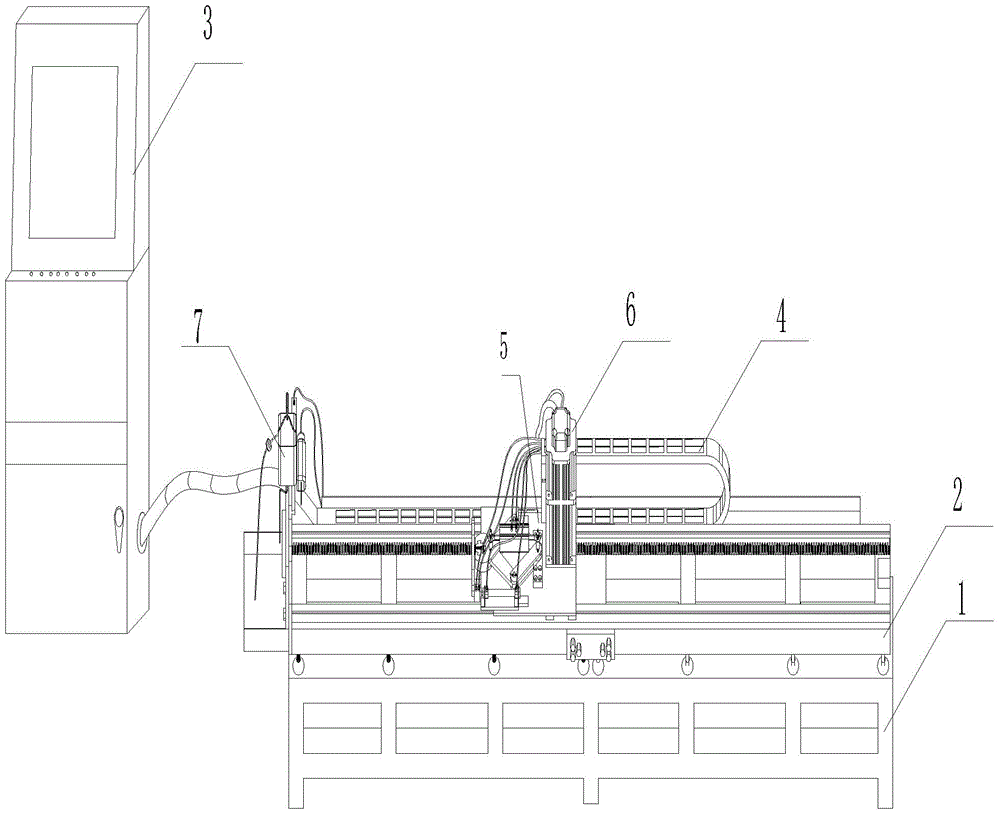
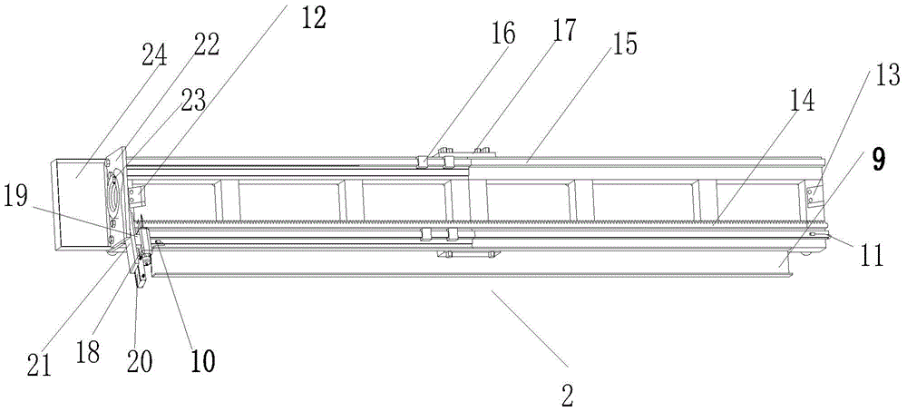
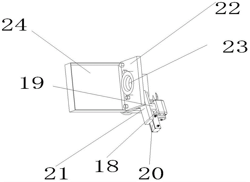
[0031] as attached Figure 1-13As shown: the present invention includes a base, on which a broaching machine is arranged, wherein: a control box is provided, and the broaching machine is provided with a drag chain of a machine tool, a clamping device, a servo motor, and a lubricating device, and the control box is connected to a lubricating device , the broaching machine is provided with a zipper fixing groove, an origin sensor and an end sensor are arranged above the zipper fixing groove, the origin sensor is located at the front end of the rack, the end sensor is located at the terminal of the rack, and above the end sensor A rack is provided, a first positioning platform and a second positioning platform are arranged above the rack, the first positioning platform is located at the front end of the rack, the second positioning platform is located at the terminal end of the rack, and a positioning platfo...


PUM


Abstract

The invention relates to a full-automatic drawing machine, and aims to provide the full-automatic drawing machine which is high in working efficiency, is low in production cost, and is intelligent. The full-automatic drawing machine comprises a base, the base is provided with a drawbench, and the drawbench comprises a control cabinet, and is provided with a machine tool drag chain, a clamping device, a servo motor and a lubricating device, wherein the control cabinet is connected with the lubricating device; the drawbench is provided with a pull chain fixing groove; an original point sensor and a terminal point sensor are arranged above the pull chain fixing groove; the original point sensor is positioned on the front end of a rack; the terminal point sensor is positioned on the terminal end of the rack; the rack is arranged above the terminal point sensor; a first positioning table and a second positioning table are arranged above the rack; the first positioning table is positioned on the front end of the rack; the second positioning table is positioned on the terminal end of the rack; a first track is arranged above the rack, and is positioned above the first positioning table and the second positioning table; a first slide table is arranged above the first track; a base connecting plate is arranged above the first slide table.

Description

technical field [0001] The invention relates to machine tools, in particular to a fully automatic drawing machine. Background technique [0002] There are currently two types of drawing machines on the market. The first type of drawing machine uses a single-sided cam to drive the drawing trolley to move, relying on the pulling force generated by the hard contact between the roller of the drawing trolley and the curved surface of the single-sided cam to realize the pulling force of the drawn trolley. The drawing of the drawing object, the stability of the drawing operation is poor; the second drawing machine is a chain dragging machine, which is mainly realized by connecting the main motor to the variable box and dragging the chain with the clamp seat and fixture The drawing operation needs to be tightened manually. After the drawing is completed, the metal needs to be cut by manpower. Finally, the drawn workpiece is manually taken down for the next drawing. The collision bet...

Claims


Application Information

Patent Timeline
Patent Type & Authority Applications(China)
IPC IPC(8): B21C1/22B21C1/30B21C9/00
CPCB21C1/22B21C1/28B21C1/30B21C9/00B21C51/00
Inventor 吴济真叶选乐叶夏磊朱贤克
Owner 金锚电力控股有限公司
Learn More