Thin-wall round pipe turning and clamping device

A clamping device and a technology for round tubes, applied in the field of mechanical processing, can solve problems such as difficulty in ensuring and controlling the size of thin-walled round tubes, affecting dimensional accuracy and shape tolerance, thermal deformation of thin-walled round tubes, etc., achieving low production costs and high processing accuracy , Ease of mass production

Inactive Publication Date: 2015-05-13
XIAN ZHIYUE ELECTROMECHANICAL TECH
View PDF0 Cites 185 Cited by
  • Summary
  • Abstract
  • Description
  • Claims
  • Application Information

AI Technical Summary

Problems solved by technology

[0002] Due to the characteristics of thin wall, poor rigidity and weak strength, thin-walled circular tubes are prone to stress deformation, thermal deformation and vibration deformation during processing.
When the thin-walled round tube is turned, it needs to be clamped by the three-jaw chuck on the lathe spindle. However, due to the thin wall, poor rigidity and weak strength of the thin-walled round tube, it is easy to deform under the clamping force of the three-jaw chuck. , which affects the accuracy requirements of its dimensional accuracy and shape tolerance. At the same time, because the thin-walled round tube is thin, the cutting heat generated during the turning process will cause thermal deformation of the thin-walled round tube, making it more difficult to guarantee and control the size of the thin-walled round tube.

Method used


Image

  • Thin-wall round pipe turning and clamping device
  • Thin-wall round pipe turning and clamping device
  • Thin-wall round pipe turning and clamping device

Examples


Embodiment Construction

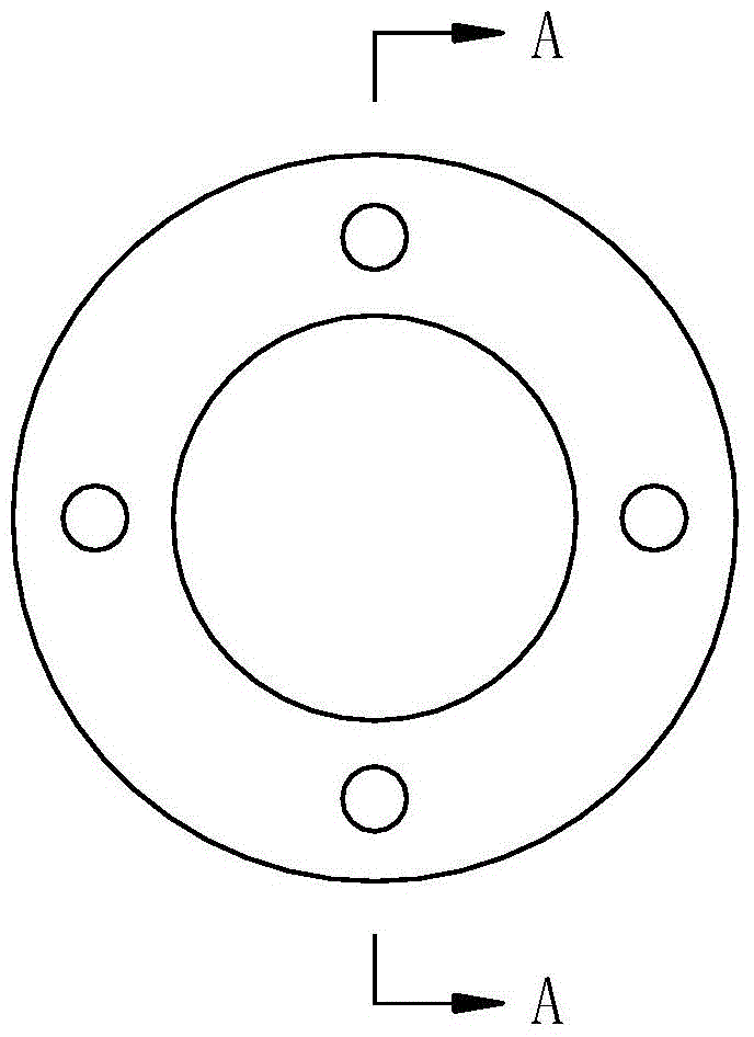
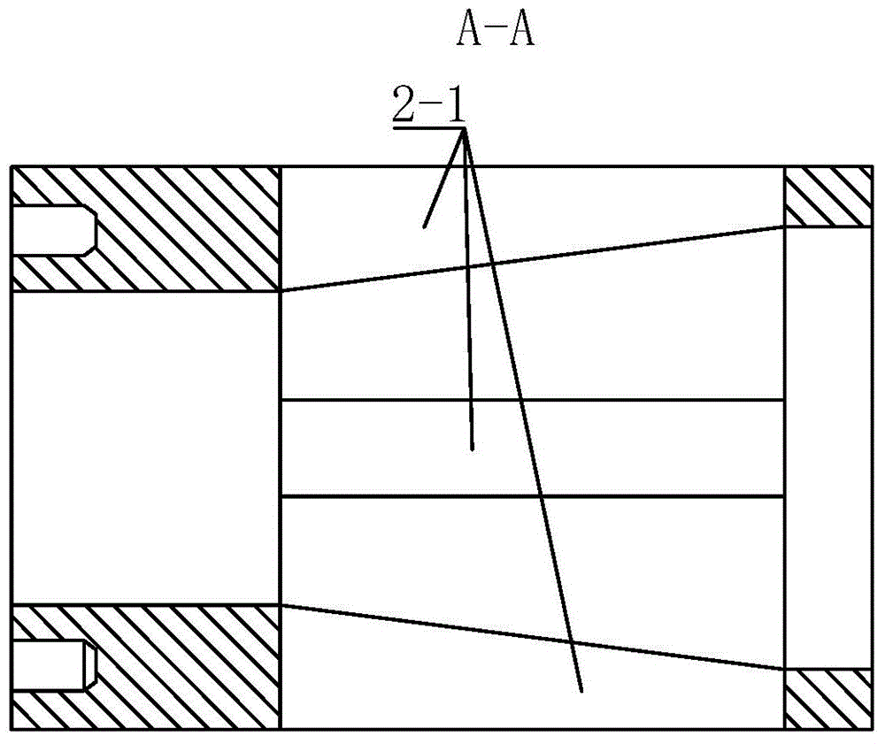
[0020] Such as Figure 1-Figure 3 The shown clamping device for turning a thin-walled circular tube includes a slider bracket 2 for slidingly installing the inclined-plane slider 4, a screw rod 7 for slidingly installing and supporting the tapered sleeve 5, and a screw rod 7 for driving the slider bracket 2 and The clamping base 1 that the screw rod 7 rotates with the main shaft of the lathe also includes an inclined plane slider 4 and a taper sleeve 5 with the same taper; the slider bracket 2 and the screw rod 7 are fixedly installed on the clamping base At one end of the seat 1, a taper sleeve 5 is slidably installed on the screw rod 7, and at least two installation chutes for installing the inclined-plane slider 4 are evenly distributed around the axis of the screw rod 7 on the slider bracket 2 2-1, each of the installation chute 2-1 is slidably installed with the tapered sleeve 5 to tighten the workpiece 3 from the inside of the inclined slider 4, each of the inclined slid...


PUM


Abstract

The invention discloses a thin-wall round pipe turning and clamping device. The thin-wall round pipe turning and clamping device comprises a slide block bracket for slidingly mounting inclined surface slide blocks, a screw rod for slidingly mounting and supporting taper sleeves, and a clamping base, wherein the slide block bracket and the screw rod are both fixedly mounted at one end of the clamping base; the taper sleeves are slidingly mounted on the screw rod; at least two inclined surface slide blocks fitting the taper sleeves to tightly eject workpieces from the inner sides are slidingly mounted on the slide block bracket; elastic cushion blocks are respectively arranged between all the inclined surface slide blocks and the workpieces; fastening nuts for tightly pressing the taper sleeves are arranged at the ends of the screw rod; and antiskid washers are arranged between the fastening nuts and the end surfaces of the taper sleeves. The thin-wall round pipe turning and clamping device has the characteristics of reasonable design, simple structure, good use effect, high machining precision, convenience for disassembly of the workpieces, low labor intensity, high production efficiency, low production cost and convenience for promotion and application.

Description

technical field [0001] The invention belongs to the technical field of mechanical processing, and relates to a clamping device, in particular to a clamping device for turning thin-walled round tubes on a lathe. Background technique [0002] Due to the characteristics of thin wall, poor rigidity and weak strength, thin-walled circular tubes are prone to stress deformation, thermal deformation and vibration deformation during processing. When the thin-walled round tube is turned, it needs to be clamped by the three-jaw chuck on the lathe spindle. However, due to the thin wall, poor rigidity and weak strength of the thin-walled round tube, it is easy to deform under the clamping force of the three-jaw chuck. , which affects the accuracy requirements of its dimensional accuracy and shape tolerance. At the same time, because the thin-walled round tube is thin, the cutting heat generated during the turning process will cause thermal deformation of the thin-walled round tube, makin...

Claims


Application Information

Patent Timeline
Patent Type & Authority Applications(China)
IPC IPC(8): B23B31/40
CPCB23B31/404
Inventor 黄冰
Owner XIAN ZHIYUE ELECTROMECHANICAL TECH
Why Eureka
Try Eureka