Friction stir welding method with controllable transition layer on the joint surface of metal composite plates
A metal clad plate and friction stir technology, which is applied in welding equipment, metal processing equipment, non-electric welding equipment, etc., can solve the problems of difficulty in ensuring that the pre-filled welding wire does not move relative to each other, poor controllability, etc., and achieves easy operation and feasibility. strong effect
- Summary
- Abstract
- Description
- Claims
- Application Information
AI Technical Summary
Problems solved by technology
Method used
Image
Examples
Embodiment 1
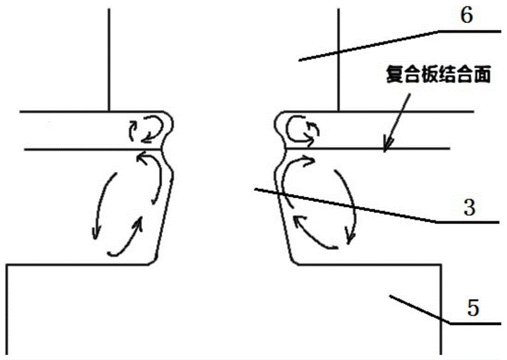
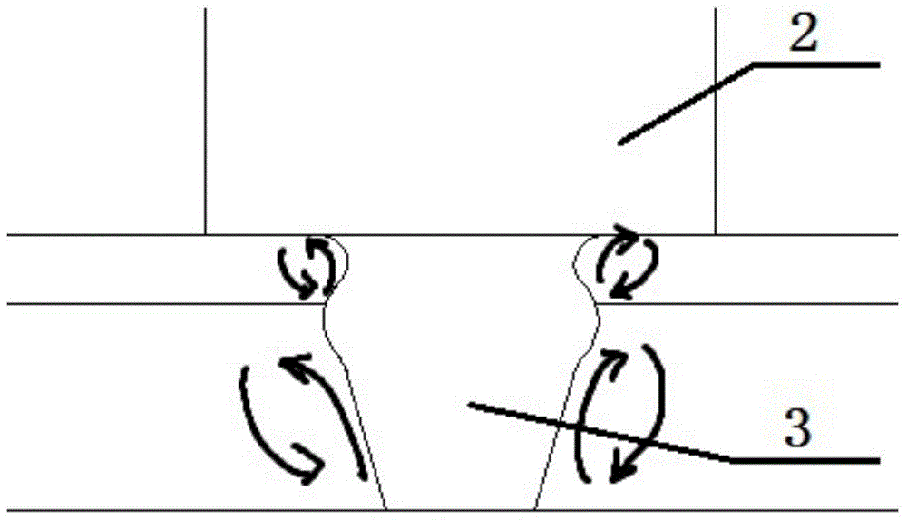
[0044] combine Figure 4 and Figure 10 , a single-shoulder stirring head with a controllable transition layer on the joint surface of a metal composite plate, comprising a clamping end 1, a shoulder 2 and a stirring pin 3, one end of the shoulder 2 is connected to the clamping end 1, and the other end is connected to the stirring pin 3 To connect, an annular protrusion 4 is provided along the circumference of the stirring needle 3 . The stirring needle 3 between the shaft shoulder 2 and the annular protrusion 4 is gradually expanding from the shaft shoulder 2 to the direction of the annular protrusion 4, and the whole stirring head is manufactured in one piece. The other end of the clamping end 1 is fixed on the main shaft of the friction stir welding machine.
[0045] The connection between the above-mentioned annular protrusion 4 and the stirring needle 3 is a circular arc transition.
[0046] Taking the welding of double-layer metal composite plates as an example, the f...
Embodiment 2
[0052] combine Figure 5 , a single-shoulder stirring head with a controllable transition layer on the joint surface of a metal composite plate, comprising a clamping end 1, a shoulder 2 and a stirring pin 3, one end of the shoulder 2 is connected to the clamping end 1, and the other end is connected to the stirring pin 3 To connect, an annular protrusion 4 is provided along the circumference of the stirring needle 3 . The stirring needle 3 between the shaft shoulder 2 and the annular protrusion 4 is tapered in shape from the shaft shoulder 2 to the direction of the annular protrusion 4, and the whole stirring head is manufactured in one piece. The other end of the clamping end (1) is fixed on the main shaft of the friction stir welding machine.
[0053] The connection between the above-mentioned annular protrusion 4 and the stirring needle 3 is a circular arc transition.
[0054] Taking the welding of double-layer metal composite plates as an example, the friction stir weld...
Embodiment 3
[0060] combine Figure 6 , a single-shoulder stirring head with controllable transition layer on the joint surface of a metal composite plate, comprising a clamping end 1, a shoulder 2 and a stirring pin 3, one end of the shoulder 2 is welded to the clamping end 1, and the other end is connected to the stirring pin 3 For welding, two annular protrusions 4 are arranged along the circumference of the stirring needle 3 . The shape of the stirring needle 3 between the shoulder 2 and the annular protrusion 4 closest to the shoulder 2 is cylindrical. The other end of the clamping end 1 is fixed on the main shaft of the friction stir welding machine.
[0061] The connection between the above-mentioned annular protrusion 4 and the stirring needle 3 is a circular arc transition.
[0062] Taking the welding of three-layer metal composite plates as an example, the friction stir welding method with controllable transition layer on the butt joint surface of metal composite plates is as f...
PUM
 Abstract
Description
Claims
Application Information
 - R&D
- Intellectual Property
- Life Sciences
- Materials
- Tech Scout
- Unparalleled Data Quality
- Higher Quality Content
- 60% Fewer Hallucinations
Browse by: Latest US Patents, China's latest patents, Technical Efficacy Thesaurus, Application Domain, Technology Topic, Popular Technical Reports.
© 2025 PatSnap. All rights reserved.Legal|Privacy policy|Modern Slavery Act Transparency Statement|Sitemap|About US| Contact US: help@patsnap.com


