Welding equipment

A technology of welding equipment and welding cavity, which is applied in the direction of welding equipment, auxiliary welding equipment, welding/cutting auxiliary equipment, etc., can solve the problems of harmful workers' health, high equipment maintenance cost, time-consuming and labor-intensive, etc., to improve welding effect and structure Simple, damage-resistant effect

Inactive Publication Date: 2017-09-26
台州市三昊车架股份有限公司
View PDF4 Cites 0 Cited by
  • Summary
  • Abstract
  • Description
  • Claims
  • Application Information

AI Technical Summary

Problems solved by technology

[0002] Metal or other thermoplastic materials such as plastics need to be connected by high-temperature welding. The traditional welding method uses manual hand-held welding torches for welding, which is time-consuming, laborious, and inefficient. The current automatic welding device is large in size, high in cost, and high in maintenance costs. Fumes harmful to the health of workers are produced during the welding process

Method used


Image

  • Welding equipment
  • Welding equipment
  • Welding equipment

Examples


Embodiment Construction

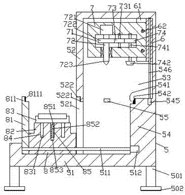
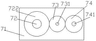
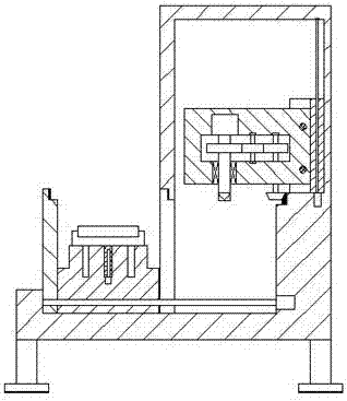
[0023] Such as Figure 1-Figure 5 As shown, a welding device of the present invention includes a welding frame 5 composed of a base 51 and a bracket 52. The inside of the bracket 52 is provided with a welding cavity 53, and the left side of the bracket 52 is close to the base 51- There is a channel 521 on the side, and the right side of the welding cavity 53 opposite to the right side of the channel 521 is fixed with a convex surface 54, and the top of the left side of the convex surface 54 is provided with a slot 541 extending forward and backward. The right side of the slot 541 is fixed with a conical toothed bar 542 extending along the front and rear extension direction of the slot 541, and the top surface of the convex surface 54 away from the slot 541 is provided with an upward extension. The first screw-shaped rod 546, the first screw-shaped rod 546 is screw-fitted and connected with the lifter 6 whose right side slides and cooperates with the right side of the welding c...


PUM


Abstract

The invention discloses welding equipment. The welding equipment comprises a welding frame composed of a basic table and a support. A welding cavity is formed in the support. A groove channel is arranged on the side, adjacent to the basic table, of the left side face of the support. A convex face portion is fixedly arranged at the position, on the right side of the groove channel, of the right side face of the welding cavity. A groove is formed in the top of the left side of the convex face portion in a front-and-back extending manner. A conic tooth strip is fixedly arranged on the right side face of the groove in the manner of extending in the front-and-back extending direction of the groove. A first screw rod extending upwards is arranged on the top face of the side, deviating from the groove, of the convex face portion. The first screw rod is in threaded fit connection with a rising and falling part with the right side face in sliding fit connection with the right side face of the welding cavity. First isolation plates are correspondingly arranged on the front side and the back side of the rising and falling part. Guide rods are arranged between the first isolation plates on the front side and the back side in an up-and-down correspondence manner. A welding implementation set extending towards the left side is in sliding fit connection to the two sets of guide rods. The welding equipment is simple in structure, welding efficiency and quality are improved, and welding safety is high.

Description

technical field [0001] The invention relates to the technical field of welding, in particular to welding equipment. Background technique [0002] Metal or other thermoplastic materials such as plastics need to be connected by high-temperature welding. The traditional welding method uses manual hand-held welding torches for welding, which is time-consuming, laborious, and inefficient. The current automatic welding device is large in size, high in cost, and high in maintenance costs. During the welding process, fumes that are harmful to the health of workers are produced. Contents of the invention [0003] The technical problem to be solved by the present invention is to provide a welding device, which can solve the above-mentioned problems in the prior art. [0004] The present invention is achieved through the following technical solutions: a welding device of the present invention, comprising a welding frame composed of a base and a bracket, the inside of the bracket is ...

Claims


Application Information

Patent Timeline
Patent Type & Authority Applications(China)
IPC IPC(8): B23K37/02B23K37/00B23K37/04B29C65/02B08B15/04
CPCB08B15/04B23K37/006B23K37/0252B23K37/04B23K37/0461B29C65/02B29C66/002
Inventor 金佳琪
Owner 台州市三昊车架股份有限公司
Why Eureka
Try Eureka