Split garbage compressor push-pull mechanism

A technology of garbage compactors and push-pull mechanisms, which is applied to presses, manufacturing tools, etc., and can solve problems such as increased labor intensity, decreased work efficiency, and inability of two hooks to hook accurately at the same time

Active Publication Date: 2016-04-13
福建精艺机械有限公司
View PDF5 Cites 0 Cited by
  • Summary
  • Abstract
  • Description
  • Claims
  • Application Information

AI Technical Summary

Problems solved by technology

When the push-pull cylinder is working, the push-pull cylinder rod pushes the buffer cylinder forward through the push plate. At this time, the buffer cylinder also starts to move, and the two claws move forward through the pin seat. Under the action of the cam at the end of the shell , open the two claws and hook the shackle of the dustbin, but due to the effect of the rigid cam, the two claws will not be completely closed due to the action of the tension spring, so it needs to be pushed back by a push-pull cylinder or a buffer cylinder Shrink a certain distance, so that the two claws also retreat a certain distance, so that the hooks on the two claws can be hooked to the shackle on the garbage bin; after running for a period of time, due to the degree of contact wear between the cam and the two claws The different and exposed tension springs are rusted, and it is easy to cause the two hooks to be unable to accurately hook the shackles on the dustbin at the same time. Therefore, it is necessary to manually hook the two hooks on the shackles of the dustbin, thereby increasing the Labor intensity also reduces work efficiency

Method used


Image

  • Split garbage compressor push-pull mechanism
  • Split garbage compressor push-pull mechanism
  • Split garbage compressor push-pull mechanism

Examples


Embodiment Construction

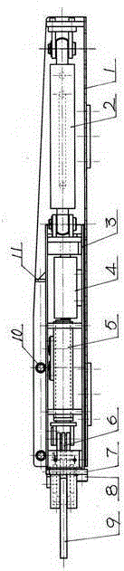
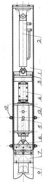
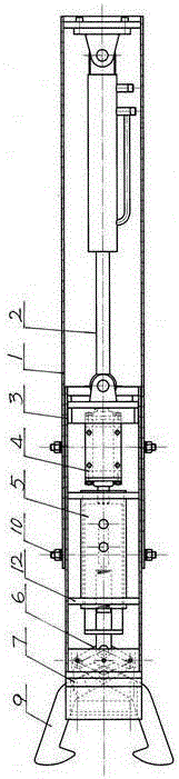
[0019] attached figure 1 , attached figure 2 , attached image 3 The push-pull mechanism of the split type garbage compressor of the present invention includes a housing, a push-pull cylinder, a buffer cylinder and a claw. The push-pull cylinder is installed in the housing, one end of the push-pull cylinder is connected to the housing, and the other end of the push-pull cylinder 2 is connected to the housing. One end of the sliding box 3 in the housing 1 is connected so that the sliding box 3 can move in the housing 1. A buffer oil cylinder 4 which plays a delay role in the pushing working state is arranged in the sliding box 3, and one end of the buffer oil cylinder 4 Contact with one end of the sliding box 3, the other end of the buffer oil cylinder 4 is in contact with one end of the limit buffer device 5 arranged in the slide box 3, and the other end of the limit buffer device 5 is movably connected with the two claws 9 through the linkage mechanism 6. The other end of ...


PUM


Abstract

The invention discloses a split sliding mechanism of a trash compressor and aims to solve the problems that the spring of the existing sliding mechanism of the trash compressor easily rusts, a hook ring on a trash box cannot be accurately hooked and operating efficiency is low. The split sliding mechanism is characterized in that the other end of a sliding cylinder (2) is connected with one end of a sliding box (3) disposed within a shell (1) and allows the sliding box (3) to move in the shell (1), a buffer cylinder (4) functioning in delaying is disposed within the sliding box (3), one end of the buffer cylinder (4) is in contact with one end of the sliding box (3), the other end of the buffer cylinder (4) is in contact with one end of a limiting buffer (5) disposed within the sliding box (3), the other end of the limiting buffer (5) is movably connected with a claw (9) through a linkage (6), and a link pin base (7) pushing the trash box to move and allowing the linkage (6) to be movably positioned is mounted at the other end, close to the limiting buffer (5), of the sliding box (3).

Description

technical field [0001] The invention relates to a split type garbage compressor, in particular to a split type garbage compressor push-pull mechanism composed of a housing, a push-pull oil cylinder, a buffer oil cylinder and claws. Background technique [0002] At present, such a split type garbage compressor clutch mechanism is disclosed on the market. Its structural features are: it includes a housing, a push-pull cylinder, a buffer cylinder and a claw. The push-pull cylinder is installed in the housing, and one end of the push-pull cylinder is connected to the housing. , the other end of the push-pull oil cylinder is in contact with one end of the buffer oil cylinder through the push plate, and the other end of the buffer oil cylinder is movably connected with the two claws through the pin shaft seat. The cam that pawl is opened, is connected with tension spring between two claws in front of the cam. When the push-pull cylinder is working, the push-pull cylinder rod push...

Claims


Application Information

Patent Timeline
Patent Type & Authority Patents(China)
IPC IPC(8): B30B9/30B30B15/00
Inventor 吴兆敏沈绍镇吴成美
Owner 福建精艺机械有限公司
Why Eureka
Try Eureka