Blocking cable lifting device

A lifting device and arresting cable technology, which is applied to ground devices, parking devices, transportation and packaging, etc., can solve the problems of no civil aircraft arresting cable system, personal and property damage, and aircraft rushing out, so as to improve combat performance, Ease of installation and maintenance, added safety benefits

Inactive Publication Date: 2019-12-20
杨文天
View PDF0 Cites 0 Cited by
  • Summary
  • Abstract
  • Description
  • Claims
  • Application Information

AI Technical Summary

Problems solved by technology

It is very likely to affect the situation in wartime
[0003] Civil aviation aircraft need to slide on the runway for a certain distance to stop safely when landing. However, due to various reasons, aircraft often rush out of the end of the runway, causing personal and property losses. Currently, there is no arresting cable system for civil aviation aircraft.

Method used


Image

  • Blocking cable lifting device
  • Blocking cable lifting device
  • Blocking cable lifting device

Examples


Embodiment 1

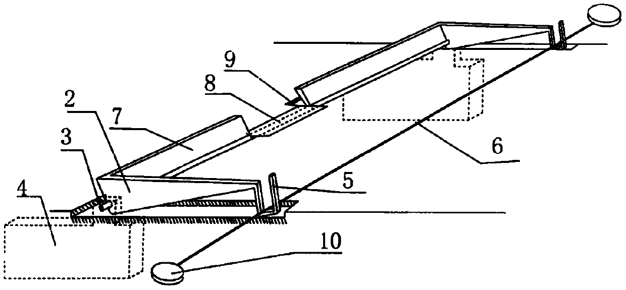
[0029] Such as figure 1 , figure 2 As shown, this is an arresting cable system using a tail hook-type arresting cable lifting device, including a trigger plate (7) with a notch welded on a long axis (3), and a hanging arresting plate welded at each end. The rocking arm (2) of the draw-in groove (5) of cable (6), the included angle of the trigger plate (7) with notch and rocking arm (2) is 110 degree. The major axis (3) is hinged on the shaft seat (4) fixed on the airstrip.

[0030] The major axis (3) spans the airstrip below the airstrip floor.

[0031] There is a gap in the middle of the trigger plate (7) with a gap for the passage of the front wheel. The gap is 2 meters wide. The trigger plate (7) is slightly tilted forward. The trigger plate (7) with notch is 30 centimeters high. Grooves are arranged at the corresponding positions where the notched trigger plate (7) is pressed down on the runway.

[0032] The upper edge of the card slot (5) is longer than the lower e...

Embodiment 2

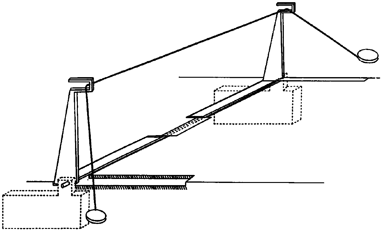
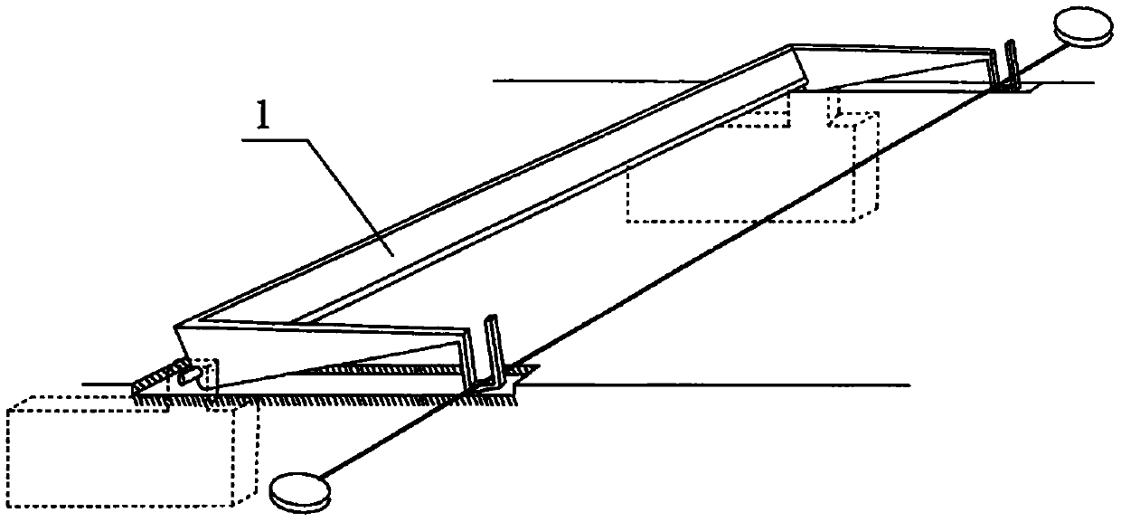
[0036] Such as image 3 , Figure 4 As shown, this is an arresting cable system that adopts the rear landing gear type arresting cable lifting device. In this embodiment, the basic structure is the same as that in Embodiment 1, and the special features are as follows:

[0037] In this embodiment, there is no gap in the middle of the trigger plate (1). When the aircraft lands, the front wheel rolls over the trigger plate (1), which drives the rocker arm (2) to rotate synchronously, and the arresting cable (6) is held up and provided to the rear landing gear.

[0038] After the aircraft lands, it travels to the lifting device of the rear landing gear type arresting cable, the front wheel rolls the trigger plate (1) to drive the rocker arm (2) to rotate, lifts the arresting cable (6), and provides it to the rear landing gear hook Hold, make the arresting cable system play a role, and realize safe landing.

[0039] This model can be installed on the runway hundreds of meters awa...


PUM


Abstract

The invention provides a blocking cable lifting device which comprises a trigger plate and a rocker arm. The two ends of the rocker arm are each provided with a clamping groove for hanging a blockingcable, and a rocker arm and trigger plate combined body is hinged to a shaft seat fixed on an air airplane runway. The arresting cable lifting device comprises a tail hook type arresting cable liftingdevice and a rear landing gear type blocking cable lifting device. When a carrier-based aircraft descends, the carrier-based aircraft runs to the tail hook type arresting cable lifting device, a front wheel passes through the gap of the trigger plate, rear wheels roll the trigger plate to drive the rocker arm to rotate, the blocking cable is lifted and hooked by a tail hook, and the blocking cable system plays a role. If the arresting cable is not hooked, when the carrier-based aircraft runs to the position of the rear landing gear type arresting cable lifting device, the front wheel rolls the trigger plate to drive the rocker arm to rotate, and the lifted blocking cable is hooked by a rear landing gear, so that safe landing is realized, and no fly-back is needed. The blocking cable system adopting the rear landing gear type arresting cable lifting device can be installed at the tail end of the civil aviation aircraft runway to prevent aircrafts from rushing out of the tail end of therunway.

Description

technical field [0001] The invention relates to the technical field of aircraft (including carrier-based aircraft) landing safety, in particular to an arresting cable lifting device. Background technique [0002] The landing runway space on an aircraft carrier is extremely limited, and the carrier-based aircraft must land at high speed in case they fail to catch the arresting cable and go around. High-speed landings come with high risks. Going around and landing again increases the risk. It is very likely to affect the battle situation in wartime. [0003] Civil aviation aircraft need to slide on the runway for a certain distance to stop safely when landing. However, due to various reasons, aircraft often rush out of the end of the runway, causing personal and property losses. Currently, there is no arresting cable system for civil aviation aircraft. [0004] There is an urgent need for a more reliable arresting cable lifting device, so that civil aviation aircraft can us...

Claims


Application Information

Patent Timeline
Patent Type & Authority Applications(China)
IPC IPC(8): B64F1/02
CPCB64F1/025
Inventor 杨文天杨立君
Owner 杨文天
Why Eureka
Try Eureka