
Rail train and shaft box structure thereof

A technology for rail trains and axle boxes, applied in the field of rail vehicles, can solve problems such as affecting the assembly relationship of various components, involving the performance of the whole vehicle, and limited space under the vehicle.

Active Publication Date: 2015-05-13
CRRC QINGDAO SIFANG CO LTD +1
View PDF8 Cites 12 Cited by
  • Summary
  • Abstract
  • Description
  • Claims
  • Application Information

AI Technical Summary

Problems solved by technology

The above-mentioned pivoting arm axle box is installed on the outside of the wheel set, that is to say, there are many parts installed on the wheel set accessories, but due to the limited space at the bottom of the vehicle, the pivoting arm axle box, brake disc, brake caliper Each component can only be arranged in a limited space, that is to say, the structure of the above-mentioned components directly affects the assembly relationship between the components, and even involves the performance of the entire vehicle

Method used


Image

  • Rail train and shaft box structure thereof
  • Rail train and shaft box structure thereof
  • Rail train and shaft box structure thereof

Examples


Embodiment Construction

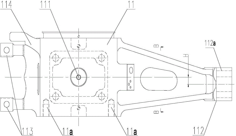
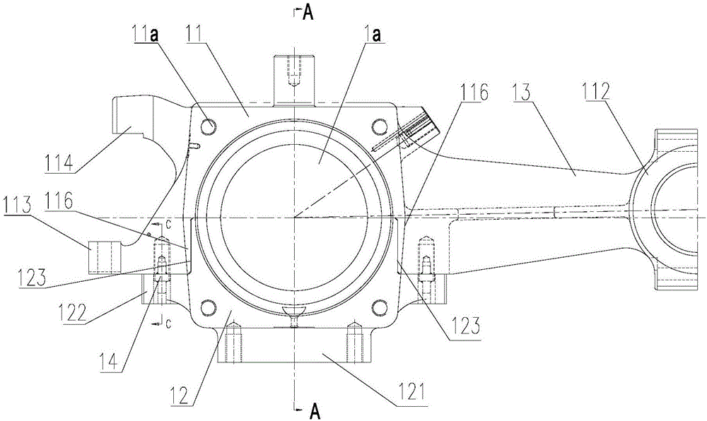
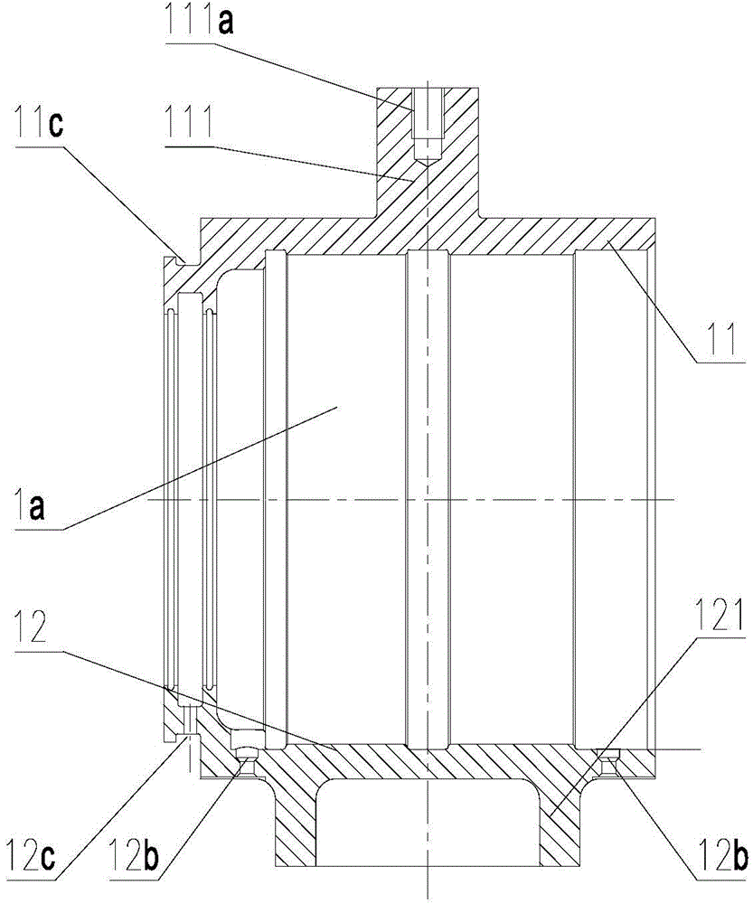
[0027] The core of the present invention is to provide a rail train and an axle box structure. By changing the specific structure of the axle box structure, the arrangement of the bottom parts of the vehicle is further optimized, and the braking reliability of the whole vehicle and the speed of wheel set replacement can be improved.

[0028] In order to enable those skilled in the art to better understand the technical solutions of the present invention, the present invention will be further described in detail below in conjunction with the accompanying drawings and specific embodiments.

[0029] Please refer to Figure 1-Figure 2 , figure 1 It is a structural schematic diagram of the axle box structure in an embodiment of the present invention; figure 2 for figure 1 Top view of the axlebox structure shown.

[0030] The present invention provides an axle box structure of a rail train, which includes an axle box body and a positioning node mounting base 112, a bearing insta...


PUM


Abstract

The invention discloses a rail train and a shaft box structure of the rail train. The shaft box structure comprises a shaft box body and a positioning joint installing base (112), a bearing installing cavity (1a) is formed in the shaft box body, the positioning joint installing base (112) is provided with an installing cavity used for installing a positioning joint, the longitudinal center line of the shaft box body is parallel to the longitudinal center face of the positioning joint installing base (112), and the longitudinal center face of the positioning joint installing base (112) deviates to the outer side relative to the longitudinal center face of the shaft box body. Accordingly, large space can be reserved for a brake clamp, and the brake clamp and a wheel pair are convenient to install and replace. Compared with the prior art, the shaft box structure is optimized, a brake clamp installing position has a larger available space, installation of relatively large brake clamps is facilitated, braking capacity is improved, and the performance of the whole train is improved. Besides, the positioning joint is installed close to the outer side so that the positioning joint can be easily installed and detached.

Description

technical field [0001] The invention relates to the technical field of rail vehicles, in particular to a rail train and an axle box structure thereof. Background technique [0002] The axle box structure is a movable joint connecting the frame and the wheel set. In addition to transmitting forces and vibrations in various directions, the axle box structure must ensure that the wheel set can jump up and down and move side to side relative to the frame to adapt to the line conditions. [0003] The axle box structure is an important part connecting the wheel set and the frame, and the axial structure generally adopts two structures of the rotary arm type and the tie rod type. At present, most rail trains adopt the pivoting arm axle box structure, wherein the pivoting arm axle box structure includes an integrated axle box and arm, that is, the pivoting arm axle box, and the pivoting arm axle box includes the axle box body and the installation of positioning nodes There is a bea...

Claims


Application Information

Patent Timeline
IPC IPC(8): B61F15/20
CPCB61F15/20
Inventor 王培东吕晓俊周平宇张振先李英明邹晓龙王大强管益辉
Owner CRRC QINGDAO SIFANG CO LTD
Learn More