A hanging frame type loose fiber dyeing machine

A technology of loose fiber and dyeing machine, which is applied in the direction of textile material contact export textile material processing, textile material carrier processing, textile material container processing, etc., which can solve the problem of easy extrusion damage to the cylinder, damage to the dyeing vat, and increased maintenance costs and other issues to achieve the effect of reducing direct collisions, increasing service life and reducing maintenance costs

Active Publication Date: 2016-08-24
广州市盟鸿机械工业有限公司
View PDF6 Cites 0 Cited by
  • Summary
  • Abstract
  • Description
  • Claims
  • Application Information

AI Technical Summary

Problems solved by technology

[0002] In the existing loose fiber dyeing machine, the fiber cage is hoisted into the dye vat, and there is no buffer device at the bottom of the dye vat, so that when the fiber cage is placed into the dye vat, it will collide with the dye vat, causing the dye vat to be damaged. At the same time, the existing There is a cylinder inside the fiber cage to ensure that the nozzle can be inserted into the cylinder for spraying, and the fiber material will not block the middle of the fiber cage. The cylinder is easy to be squeezed and damaged. After damage, the fiber needs to be removed Cage replacement and fiber cage replacement costs are high. At the same time, most of the existing loose fiber dyeing machines use circulating pumps to recycle dyes. Cleaning and maintenance are required, increasing maintenance costs
[0003] Moreover, the existing hanging frame dyeing machines generally place the loose fiber cakes in the fiber cage, and the fiber cage is generally open at the top, so that after hanging It is necessary to cover and close the cover, and the hoisting sling needs to be disassembled, which is very troublesome

Method used


Image

  • A hanging frame type loose fiber dyeing machine
  • A hanging frame type loose fiber dyeing machine

Examples


Embodiment Construction

[0018] The present invention will be described in detail below in conjunction with accompanying drawings and specific preferred embodiments, so that the advantages and features of the present invention can be more easily understood by those skilled in the art. range is limited.

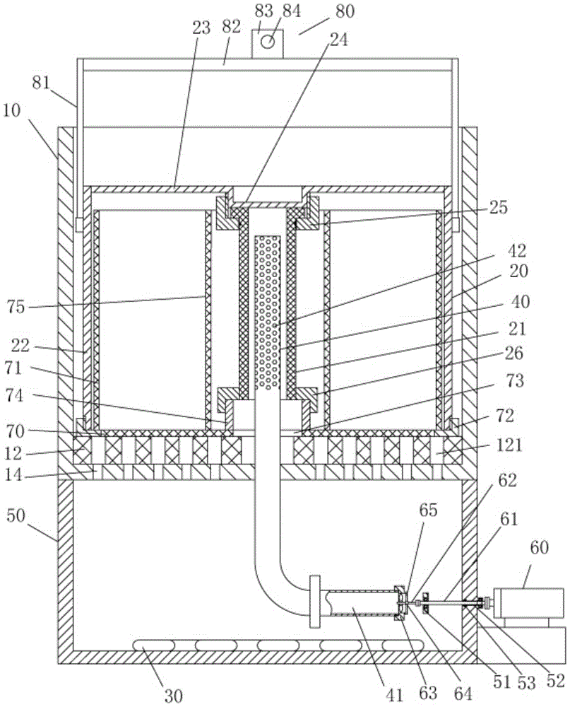
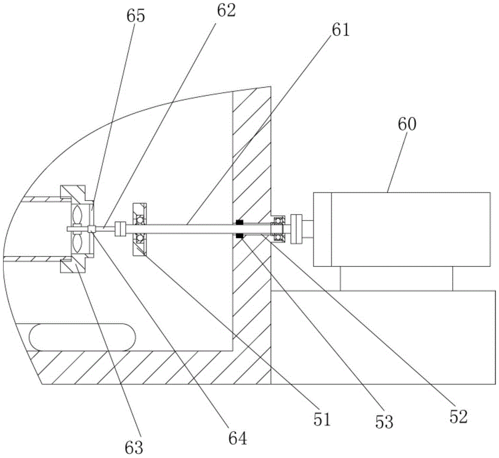
[0019] Examples, see e.g. Figures 1 to 2 Shown, a hanging frame type bulk fiber dyeing machine, comprising a dye vat 10, a fiber cage 20, a heating coil 30 and a central nozzle 40, the bottom of the dye vat 10 is fixed with a dye tank 50, and a heating plate is fixed in the dye tank 50 Pipe 30, the outer wall of dye tank 50 is fixed with drive motor 60, and the output shaft of drive motor 60 is connected with intermediate rotating shaft 61 by coupling, and intermediate rotating shaft 61 stretches in the dye tank 50, and intermediate rotating shaft 61 is fixed on by bearing. On the dye tank 50, the other end of the intermediate rotating shaft 61 is connected with the central shaft of the propeller 62...


PUM


Abstract

The invention discloses a novel hanging frame type loose fiber dyeing machine which comprises a dye vat, a fiber cage, a heating coil and a central spray pipe, wherein a dye tank is fixed at the bottom of the dye vat; the heating coil is fixed in the dye tank; a driving motor is fixed on the outer wall of the dye tank; the fiber cage is placed in the dye vat; the bottom of the fiber cage is in threaded connection with a fiber cage cover; a built-in sleeve is fixed on the top surface of the fiber cage cover; the built-in sleeve is inserted in the fiber cage; a lifting mechanism is fixed at the top of the fiber cage; the fiber cage cover is pressed on a cushion fixed on the bottom plate of the dye vat; the upper end of the central spray pipe penetrates through the cushion and the fiber cage cover and extends into a middle upright pipe body of the fiber cage; spray holes are formed in the side wall at the upper end of the central spray pipe. According to the novel hanging frame type loose fiber dyeing machine, a lifting appliance doesn't need to be dismounted after the fiber cage is placed on the dye vat, the novel hanging frame type loose fiber dyeing machine is simple and convenient as the dye vat doesn't need to be equipped with a vat lid, and the dye vat is provided with a cushion mechanism so as to reduce direct collisions caused when the fiber cage is lifted and prolong the service life.

Description

Technical field: [0001] The invention relates to the technical field of textile printing and dyeing equipment, in particular to a hanging frame type loose fiber dyeing machine. Background technique: [0002] In the existing loose fiber dyeing machine, the fiber cage is hoisted into the dye vat, and there is no buffer device at the bottom of the dye vat, so that when the fiber cage is placed into the dye vat, it will collide with the dye vat, causing the dye vat to be damaged. At the same time, the existing There is a cylinder inside the fiber cage to ensure that the nozzle can be inserted into the cylinder for spraying, and the fiber material will not block the middle of the fiber cage. The cylinder is easy to be squeezed and damaged. After damage, the fiber needs to be removed Cage replacement and fiber cage replacement costs are high. At the same time, most of the existing loose fiber dyeing machines use circulating pumps to recycle dyes. Cleaning and maintenance are requ...

Claims


Application Information

Patent Timeline
Patent Type & Authority Patents(China)
IPC IPC(8): D06B1/08D06B23/14D06B23/04
CPCD06B1/08D06B23/04D06B23/14
Inventor 马晓均
Owner 广州市盟鸿机械工业有限公司
Why Eureka
Try Eureka